128-9364
11 of 28
11
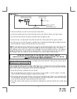
16 Dark Blue Wire: (-)
300mA Pulsed Channel 3 Output (Trunk)
The Dark Blue wire supplies a 300mA ground pulsed output whenever channel three of the receiver is
accessed. Pressing the pre-programmed transmitter button for three seconds will access channel three.
This is a low current output and must be connected to a relay to supply power to the trunk release or the
circuit you wish to control. Connect the Dark Blue wire to terminal # 86 of a 30 amp automotive relay
Connect terminal # 85 of the relay to a fused + 12 volt source. Connect the common, normally open,
and normally closed contacts of the relay to perform the selected function of channel 3.
17 Green w/ Black trace Wire:
300mA Pulsed Channel 4 Output
The Green w/ Black Trace wire supplies a 300 mA switched output whenever channel four of the receiver
is accessed. Pressing the pre-programmed transmitter button(s) will provide a 1 second pulse to channel
four This is a low current output and must be connected to a relay to supply power to the device you intend
to control. Connect Green w/ Black Trace wire to terminal #86 of a 30 amp automotive relay. Connect
terminal #85 of the relay to a fused + 12 volt source. Connect the common, normally open, and normally
closed contacts of the relay to perform the selected function of the channel 4 output.
NOTE:
This wire also can be used for defrost activation as dictated by the setting of feature # 1 of Bank 3.
Anytime the vehicle is running under control of the Remote Start and Channel 4 is activated, then depen-
dent on the selection of this feature, Green/Black will be activated for a 1 second pulse, or for 10 minutes.
NOTE:
This wire will, as a defrost output, only operate when running under control of the remote start, it
will not operate when the vehicle is running under the control of the ignition key.
When the key & remote start are off, the output will operate as indicated above.
18 Green w/ White trace Wire:
Entry Illumination Ground Output
This wire provides a 30 second ground output, (300 mA Max.), whenever the remote is used to disarm the
alarm or to unlock the doors. It also provides a continuous pulsed output whenever the alarm is triggered.
This wire should be connected to an external relay and wired to the vehicles interior entry lighting circuit
whenever the optional Entry Interior Illumination feature is desired.
19 Black w/ White trace Wire:
300 mA Horn Output
The black w/ white trace wire is provided to beep the vehicle’s horn. This is a transistorized low current
output, and should only be connected to the low current ground output from the vehicle’s horn switch.
If the vehicle uses a + 12 VDC horn switch, then connect the black w/ white trace wire
to terminal 86 of a 30Amp automotive relay, and connect relay terminal 85 to a fused
+ 12 VDC battery source. Connect relay terminal 87 to the vehicle’s horn switch output, and connect relay
terminal 30 to a fused + 12 VDC battery source.
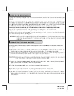
20 Orange Wire:
300mA (-) Ground When Armed Output
This wire provides a 300 mA ground output when the alarm circuit is armed to control the starter inhibit
relay. Connect the Orange wire to terminal #86 (orange wire) of the relay provided. Connect terminal
#85 (red wire) of the relay to an ignition wire in the vehicle that is +12 volts when the ignition switch is
turned to the on and start positions and off when the key is off. Locate and cut the low current start so-
lenoid wire found at the vehicles ignition switch harness. This wire will have + 12 volts when the ignition
key is moved to the start (crank) position and will have 0 volts in all other key positions. Connect one
side of the cut wire to terminal #87a ( Black wire) of the relay. Connect the other side of the cut wire to
terminal #30 (White/Black wire) of the relay. Refer to the detail wiring; also see Yellow Start wire detail
for connection to vehicle considerations.
Summary of Contents for APS-922E
Page 27: ...128 9364 27 of 28 27 NOTES ...


