background image

49

4 Controls 

4.6 

Main Output Bus

StudioLive™ 32.4.2AI 

Owner’s Manual

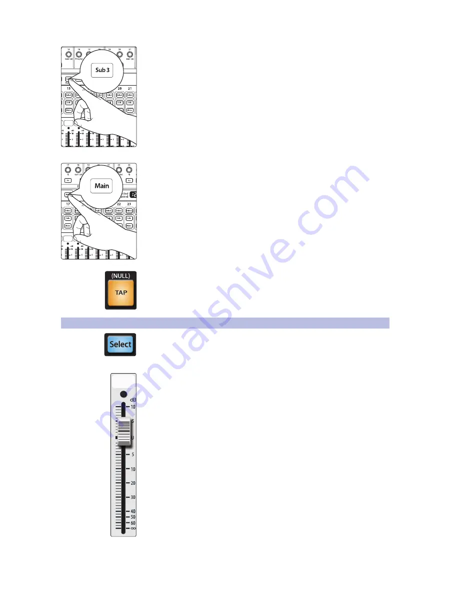
7.  Press the Select button for FX C and assign this bus to Subgroup 3 and unassign it 

from the Main bus. If you like you can also add some dynamics processing and EQ 
at this point. 


8.  Press the Select button for Subgroup 3 and assign the group to the Main output. 

(Because a delay can increase the signal’s volume quite dramatically, you may want 
to experiment with the delay at its most intense setting, with FX C’s output turned 
up, and use the limiter for Subgroup 3 to keep the level under control.)

The vocal-delay level is now controlled by the Subgroup 3 fader, and you can use it 
to season the reggae band’s performance. 


The Tap button allows you to go one step further and set the tempo of the delay to 

match the tempo of the song. 


4.6 

Main Output Bus

Main Select Button. Enables Fat Channel Viewing.
As previously described in 

Section 4.1.1

, the Select button routes its channel 

through the Fat Channel, allowing you to add dynamics processing, EQ, panning, 
etc. This will also open the Channel Info page for the Main bus in the LCD.
Main Fader. Controls the Level of the Main Output.
The fader controls the overall level of the main stereo and mono outputs.
The white area above the fader can be used as a scribble strip Use only 
oil pencils. Other types of pens or pencils cannot be wiped off.
To clean the scribble strip, use a lightly damp cloth to remove the writing. Spit works 
pretty well, too. 


Summary of Contents for StudioLive AI-Series

Page 1: ...StudioLive AI Series Mixers Digital Mixing System with Active Integration Owner s Manual www presonus com English ...

Page 2: ...hannel Presets 32 4 1 11 Channel Presets Library 34 4 2 Metering 35 4 2 1 StudioLive Fat Channel Metering Controls 35 4 2 2 Subgroup and Main Meters 36 4 2 3 A Quick Note About dBu and dBFS 36 4 3 Input Channel Strip 37 4 3 1 Input Channel Controls 37 4 4 Aux and FX Buses 38 4 4 1 Analog Aux Bus Controls 38 4 4 2 Internal FX Bus Controls 39 4 4 3 Aux and FX Bus Channel Sends 39 4 4 4 Pre Post Chan...

Page 3: ... Scene Recall 69 5 3 5 Fader Locate 71 5 3 6 Quick Scenes StudioLive 32 4 2AI only 71 5 3 7 AutoStore 73 5 4 Graphic Equalizers 73 5 4 1 The GEQ Menu 74 5 4 2 Saving and Loading Graphic EQ Presets 75 5 5 System Menu 77 6 Resources 81 6 1 Stereo Microphone Placement 81 6 2 Compression Setting Suggestions 84 6 3 EQ Frequency Guides 86 6 4 EQ Setting Suggestions 88 6 5 Technical Specifications 90 6 6...

Page 4: ...iv ...

Page 5: ...ve LED metering mixer save recall channel strip save recall copy paste talkback and more StudioLive breaks new boundaries for music performance and production All you need is a compatible computer with a FireWire connection a few microphones and cables speakers and your instruments and you are ready to record in the studio or in front of a live audience We encourage you to contact us with question...

Page 6: ... setting suggestions and are included to help you get the most from your StudioLive mixer Thank you once again for buying our product We are confident that you will enjoy your StudioLive 1 3 Summary of StudioLive AI series Mixer Hardware Features 24 bit resolution up to 48 kHz sampling rate 32 24 16 Class A XMAX microphone preamplifiers with individual phantom power 32 24 16 line level inputs 32 2...

Page 7: ...ing software Studio One Artist digital audio workstation with more than 6 GB of plug ins loops and sounds 1 4 What is in the Box In addition to this manual your StudioLive package contains the following PreSonus StudioLive AI series digital recording and performance mixer StudioLive AI Software Library Reference Manual 6 foot 1 8 meter 9 pin to 9 pin FireWire s800 cable IEC power cord USB wireless...

Page 8: ...olume Do not allow your inputs to clip Watch the level meters when the LEDs near the Clip mark the top LED will illuminate indicating that the analog to digital converters are in danger of being overdriven Overdriving the converters will cause digital distortion which sounds terrible The XMAX preamps in your StudioLive provide plenty of headroom take advantage of it Your P A and studio equipment s...

Page 9: ... you re using passive speakers connect them to your power amplifier using speaker cable 4 Bring down all the faders on your StudioLive to the setting 5 Make sure that the Mic Line knob on Channel 1 is all the way counter clockwise 6 Plug your StudioLive into a power outlet and turn it on ...

Page 10: ... your microphone requires phantom power engage the 48V button on Channel 1 of your StudioLive 8 Turn on your amplifier or powered monitors 9 Press the Input button in the Meter section 10 Speak or sing into your microphone at approximately the same volume you expect during the performance ...

Page 11: ...Adjust the Channel 1 trim knob until a little more than half of the green LEDs are lit The red LED at the top of the meter should never light up 12 Press the Select button on Channel 1 13 Raise the Channel 1 fader until it reaches U unity gain 14 Press the Main button in the Assign section of the Fat Channel so that it illuminates This routes the channel to the main output bus ...

Page 12: ...ng Procedure StudioLive 32 4 2AI Owner s Manual 15 Bring up the Main fader until you can comfortably listen to your microphone through your speakers 16 With Channel 1 selected you can use the Fat Channel to add dynamics processing and EQ ...

Page 13: ...ING Phantom power is required for condenser microphones but can severely damage some dynamic mics especially ribbon mics Therefore switch phantom power off for all channels where it is not required Power User Tip Dynamic microphones and ribbon microphones are generally lower output devices and require no external power source The most important thing to note about ribbon microphones is that they v...

Page 14: ...nnel s gain control but before the digital bus The return goes straight to the digital bus So if you insert a de esser on your vocalist s channel you will be sending an unprocessed amplified signal to the de esser the processed signal returned to the StudioLive will then be routed to the digital bus where it can be sent through the Fat Channel Aux and FX buses etc Insert connector wiring Tip send ...

Page 15: ...See Auxiliary Digital Sends in the StudioLive AI Series Software Library Manual for details Talkback Mic Level This is the trim control for your talkback microphone It adjusts the gain of the talkback input Mono Output This balanced output carries a mono summed version of the stereo signal from the Main bus Mono Output Level This knob controls the maximum level of the Mono Output signal The signal...

Page 16: ... These outputs are post gain pre insert and pre A D converter Only the microphone preamps and line level inputs are available through the direct outputs The digital returns cannot be patched to the direct outputs DB25 pin outs H Hot C Cold G Ground Power cable Input This is where you plug in the provided IEC power cable Power Switch Push the top part of the switch to turn on your StudioLive Push t...

Page 17: ...ioLive from virtually anywhere This is especially useful when your wireless control devices iPad iPhone or iPod touch must be used in a different room from where your StudioLive is installed or if there is quite a bit of wireless interference in your venue For more information on connecting your StudioLive to a LAN network please review Networking your StudioLive Mixer in the StudioLive AI Series ...

Page 18: ...agrams WARNING Power down unit before removing option card front of house speakers laptop running Capture 2 0 subwoofer wireless router StudioLive control surface iPad running SL Remote AI USBWireless LAN adapter iPhones running QMix AI WIFI acoustic guitar DI sax keyboard DI lead vocal backup vocal mics ...

Page 19: ...15 3 Hookup 3 3 Typical Band Setup Diagrams StudioLive 32 4 2AI Owner s Manual wireless in ear keys wireless in ear lead vocals floor wedges sidefill drum monitor drum kit bass DI electric guitar amp ...

Page 20: ... s Manual 3 4 Typical Church Setup Diagrams dvd player keyboard DI piano lead vocal backup vocal mics podium mic hanging choir mics acoustic guitar DI WARNING Power down unit before removing option card front of house speakers laptop running Capture 2 0 cry room subwoofers ...

Page 21: ...AI Owner s Manual wireless router iPads running SL Remote AI iPhones running QMix AI drum kit bass DI electric guitar amp rhythm electric guitar amp lead floor wedges wireless in ear lead guitar wireless in ear bass wireless in ear keys wireless in ear lead vocals ...

Page 22: ...cts buses each of the subgroups both auxiliary inputs and the main output bus Each of these buttons serves exactly the same purpose to access the available Fat Channel parameters for its channel or bus It should be noted that while the noise gate compressor EQ and limiter are available on every input channel and bus the high pass filter is only available on the input channels aux buses and interna...

Page 23: ...Mic Solo Bus 4 1 3 Fat Channel Dynamics Processing and EQ The main function of the Fat Channel is to provide dynamics processing and filtering for every input and output on the StudioLive The rotary encoders work in conjunction with the meters directly above them to adjust and display the dynamics processing and EQ parameters The Fat Channel s processing section consists of five parts high pass fi...

Page 24: ...p In practice expanders and noise gates are used almost identically The main difference is that an expander is smoother and more gradual so that it is easier to set the attack and release times correctly Gate Key Listen Button 32 4 2AI and 24 4 2AI only Enables Key Listen in the Solo Bus This button engages and disengages the Key Listen function in the solo bus It will illuminate to indicate that ...

Page 25: ...ill never click Gate Release Sets and Displays the Rate at Which the Gate Closes on the Selected Channel This encoder sets and the meter displays the rate at which the gate for the selected channel closes The release time can be set from 0 05 to 2 seconds Power User Tip Gate release times should typically be set so that the natural decay of the instrument or vocal being gated is not affected Short...

Page 26: ... compression immediately when a signal exceeds the threshold You can set the attack from 0 2 to 150 milliseconds Compressor Release Sets and Displays the Compressor Release Setting for the Selected Input Channel or Output Bus This encoder sets and the meter displays the release setting of the compressor for the selected channel or output bus Release sets the length of time the compressor takes to ...

Page 27: ...he center frequency is constant the bandwidth is inversely proportional to the Q so as you raise the Q you narrow the bandwidth Low EQ Gain Control Sets and Displays the Gain Attenuation or Boost of the Center Frequency This encoder sets and the meter displays the gain cut or boost at the center frequency for the Low band The level of the center frequency can be set between 15 and 15 dB Low Shelf ...

Page 28: ...the Low Mid Frequency Band This button will narrow the Q of the Low Mid Band to 2 0 to provide more exact control By default the Low Mid Q is set to 0 55 Low Mid EQ Gain Control Sets and Displays the Gain Attenuation or Boost of the Center Frequency for the Low Mid Band This encoder sets and the meter displays the Gain cut or boost at the center frequency of the Low Mid band The level of the cente...

Page 29: ...coder sets and the meter displays the gain cut or boost at the center frequency of the High Mid band The level of the center frequency can be set between 15 and 15 dB High EQ On Off Button Turns the High EQ On Off for the Selected Input or Output Bus This button activates the High band for the selected channel or bus The button will illuminate to indicate control is active The High EQ band is avai...

Page 30: ... selected shelving frequency Power User Tip A high shelving EQ is like a treble control knob on a stereo In this mode the Center Frequency control selects the shelving frequency Limiter On Off Turns on the Limiter for the Selected Input Channel or Output Bus When the limiter is engaged the button will illuminate The ratio is 1 The Limiter is available for all 32 24 16 input channels and every outp...

Page 31: ...ck drum to the bass channel can tighten up a good rhythm section and make them sound even better it will not correct timing issues and will actually exaggerate them if your bass player and drummer aren t in the pocket For this purposes of this Tutorial we will be sidechaining the kick drum on Channel 1 to the bass on Channel 15 1 Press the bass channel s Select button 2 In the Fat Channel s Gate s...

Page 32: ...ut having to struggle to re create your old standby and after several minutes of careful adjustment you can verify that a new Fat Channel setting is better than it was before you started tweaking To A B Fat Channel settings 1 Select a channel and create a Fat Channel setup 2 Press the Alt EQ Dyn button The button will light up to alert you that you are using the Alt Fat Channel layer 3 Dial in a n...

Page 33: ...reo link can be enabled when either channel in the pair is selected When the Stereo Link button is illuminated all dynamics settings except Polarity Invert subgroup assignments and main assignments are destructively pasted to the other channel in the pair 4 1 7 Fat Channel Subgroup and Main Output Assignments Output assignments are set within the Fat Channel It should be noted that the StudioLive ...

Page 34: ...ton to copy the settings on the selected channel or bus Every Select button on the StudioLive except the button for the currently selected channel will begin to flash The Select button for the selected channel will not illuminate You can copy a Fat Channel setting from any channel or bus to any combination of channels and buses The Load button will also start to flash 2 To paste the current channe...

Page 35: ...elected channel onto which the preset will be loaded Use the Value encoder to locate scroll through the preset library You can also press the Next button to scroll through preset categories You can choose from DRM Drum BAS Bass GTR Guitar KEY Keyboards HRN Horns PRC Percussion VOX Vocal SYS System MIS Miscellaneous Once you have selected the category press the Next button and use the Value encoder...

Page 36: ...ess the Fat Channel s Save button 1 You will notice that the LCD will display the Channel Preset Save menu Use the Value encoder to scroll to an empty position in the Channel Preset library 2 Press the Next button to navigate to the category location 3 Use the Value encoder to scroll to the category in which your preset would fit DRM VOX GTR etc 4 Press the Next button again to navigate to the fir...

Page 37: ... with uppercase and lowercase letters as well as a selection of numerals and punctuation marks You can insert a space by simply pressing the Tap button 6 Once you are satisfied with your changes press the Store button It will illuminate while the Channel preset is being written to the StudioLive s internal memory Once the Channel preset is saved the Store button will return to its unlit state ...

Page 38: ... KEY Piano Warm 05 DRM Kick Hip Hop 31 KEY Piano Jazz 06 DRM Kick Jazz 32 KEY Piano Electric 07 DRM Snare 1 33 KEY Piano Electric 2 08 DRM Fat Snare 34 KEY Vibes 09 DRM Snare Crackalak 35 HRN Trumpet 10 DRM Snare Snappy 36 HRN Trombone 11 DRM Toms Mid 37 HRN Sax 12 DRM Toms Low 38 HRN Sax Solo 13 DRM Toms High 39 PRC Congas 14 DRM Overhead Rock 40 PRC Bongos 15 DRM Overhead Jazz 41 PRC Cowbell 16 ...

Page 39: ... that the meters simply overlay the selected Fat Channel state For instance if you have Channel 16 selected and then press the Output button in the Meter section the knobs and buttons in the Fat Channel section will still be active The advantage of this is that you can make adjustments in the Fat Channel while monitoring your entire mix Input Metering Button Turns PFL Input Metering On and Off Swi...

Page 40: ... value cannot be determined dBFS or decibels relative to full scale is used to measure amplitude levels in digital systems that have a maximum peak level the point at which the A D converter will clip When measuring in dBFS 0 dBFS cannot be exceeded 0 dBFS can equal 10 to 24 dBu depending on the device s maximum peak level For StudioLive series mixers 0 dBFS equals 18 dBu in the subgroups and 24 d...

Page 41: ...t level to prevent any signal degradation Digital Return Button Turns Digital Playback Streaming On Off The Digital Return button routes a playback stream from your audio software to the StudioLive s channel inputs where it is routed and processed the same way as analog input signals For example if you want a particular recorded track to play on mixer Channel 3 simply route that track in your audi...

Page 42: ...ternal effects processors into the mix As with the other buses the StudioLive allows you to add global dynamics processing and EQ to these aux buses The analog aux buses are mono however two aux buses can be linked to create a stereo bus 4 4 1 Analog Aux Bus Controls Solo Button Turns Soloing On Off This button will solo the aux bus to the monitor outputs Only PFL soloing is available for the aux ...

Page 43: ... in the Fat Channel When the Mix button is pressed once the 32 24 16 encoder knobs in the Fat Channel become the aux send level controls for each of their respective input channels The meters will display the send amount for each of the input channels Aux Flip Mode Enables Aux Send Level Control for Main Digital return Tape In Aux Ins A and B FXA FXB FXC FXD and Talkback Pressing the Mix button a ...

Page 44: ...or wedges as compression can cause feedback problems 4 4 5 Creating Monitor Mixes Creating custom monitor mixes is critical If musicians can t hear themselves or their bandmates their performance will suffer A monitor mix can be mono or stereo Most often an individual live monitor mix is mono and is sent to a floor wedge or sidefill monitor The obvious exception is in ear monitor systems A studio ...

Page 45: ...First several channels can be sent to a single processor In addition to greatly simplifying the number of parameters you have to control this can create a cohesive sound in your mix The second advantage of creating an effects mix is that you can vary the level sent from each channel to the processor rather than patching the output directly into the effect This allows you to add a lot or a little o...

Page 46: ...each input to the reverb but you probably will not want much of the drums and bass to be processed as too much reverb could reduce their impact and leave your mix without a sturdy foundation So rather than turning the aux send level for the kick drum channel all the way up turn it so that the meter reads between 20 and 30 saturation This way only a small portion of the kick drum input will be affe...

Page 47: ...se Aux 1 to feed an external effects processor 1 To begin connect the Aux 1 output to the input of your external effects processor and connect the outputs of your processor to Aux In A of your StudioLive as illustrated 2 Turn the Output knob in the Aux 1 section to Unity 3 Press the Aux In A Select button LINE INPUT MIC INPUT BALANCED OUTPUTS MIDI PEDAL DIGITAL I O MONO Balanced Input LEFT RIGHT D...

Page 48: ...to set the send levels for each channel to the effects processor the same way you used them to create a monitor mix As with creating an internal FX mix the higher a channel s level is in the FX mix the more processed wetter it will sound 6 Once you have determined your effects mix you can press the Select button for Aux 1 to add dynamics processing and EQ to the aux mix before it is sent to the ex...

Page 49: ...ustments for a Subgroup As previously described in Section 4 1 1 the Select button routes its subgroup through the Fat Channel allowing you to add dynamics processing EQ panning etc or to patch a subgroup to the Main bus This will also open the Channel Info page for the selected subgroup in the LCD Solo Button Turns Soloing On Off for the Subgroup Bus This button will solo its subgroup to the moni...

Page 50: ...nnel 3 Snare Bottom Channel 4 Floor Tom Channel 5 Tom 1 Channel 6 Tom 2 Channel 7 Overhead Left Channel 8 Overhead Right Channel 9 Hi Hat We will create a stereo subgroup by linking Subgroups 1 and 2 1 The first step in creating a subgroup is to get a good mix of the instruments you are grouping in this case the drums Beginning with Channel 1 Kick raise the fader and with the drummer s assistance ...

Page 51: ...is is especially useful when employing specialty or signature effects For instance a typical vocal mix for an electronic band dramatically trails off in a wash of reverb whereas a reggae band usually has delay on vocals The StudioLive allows you to assign any of the onboard effects buses to a subgroup There are several advantages to assigning an effect like delay or reverb to a subgroup rather tha...

Page 52: ...er Detail page This will display every parameter available for the preset that was loaded and you can adjust its parameters to taste See Section 5 1 for complete operating instructions 5 Next decide which channels should be sent to the effects bus In dub and reggae music the vocals are most often sent to a delay so let s send our two vocalists on Channels 10 and 11 to that delay To assign the voca...

Page 53: ...er and you can use it to season the reggae band s performance The Tap button allows you to go one step further and set the tempo of the delay to match the tempo of the song 4 6 Main Output Bus Main Select Button Enables Fat Channel Viewing As previously described in Section 4 1 1 the Select button routes its channel through the Fat Channel allowing you to add dynamics processing EQ panning etc Thi...

Page 54: ...e StudioLive mixer Press it again to unmute them If you unmute a channel while the All On group is active the All On button will blink to alert you that the mute group has been altered All Off Button Clears all Mutes When the All Off button is pressed any channel or bus that has been muted will be unmuted Mute Group 1 6 buttons Engages Disengages assigned Mute Groups When any of the Mute Group but...

Page 55: ...o different effects at the same time You also can patch processed return signals from an external effects processor using Aux Inputs A and B Power User Tip Aux Inputs A and B can also be used as stereo line input channels for line level devices like keyboards synths and amp modelers Because Aux Inputs A and B can be processed by the Fat Channel and sent to any aux mix they should be used as extra ...

Page 56: ...ned and unassigned to multiple Aux buses at once each Aux mix provides its own individual level control for the talkback via Aux Flip mode See Section 4 4 3 for details Talkback Button Turns the Talkback Mic On Off This latching button turns the talkback mic on and off It will illuminate to indicate that the talkback mic is active When illuminated the talkback mic signal will be patched to all ass...

Page 57: ...nnel or bus routes that channel to the Solo bus and has no effect on the main or subgroup mixes PFL soloing is not available for the subgroups Aux bus soloing is always PFL regardless of whether this mode is engaged SIP Solo In Place On Off Button Enables Solo In Place SIP Solo In Place or destructive soloing mutes every unsoloed channel on the StudioLive If one of the muted channels is routed to ...

Page 58: ...y patch one input or bus to the monitor bus at a time Latch Solo and Radio Solo modes allow the Monitor bus to function as a summing amp See Section 4 10 for details 4 9 3 Solo Clear To clear all solos on your StudioLive press and hold the Tap Tempo button while simultaneously pressing any Solo button the mixer All Solo buttons will be disengaged 4 9 4 Using the Solo Bus for Monitoring When mixing...

Page 59: ...ne on stage is picking up the bass signal To determine the cause solo only the aux send in question and again select the Solo button for the monitors headphones You can now listen to exactly the same mix as your troubled vocalist and can fix his monitor mix quickly This application is also useful in heading off a feedback problem 4 9 5 Using Solo in Place SIP to Set Up a Mix We started this manual...

Page 60: ...work from the bottom up so press the Solo button on your kick drum mic channel Notice that all the other channels on your StudioLive have been muted and the kick drum channel is selected 5 The Fat Channel will display the dynamics processing EQ output routing and pan settings for the kick drum 6 Using the encoders and meters in the Fat Channel set up the compressor and EQ for this channel Kick Sna...

Page 61: ...the signal from the tape inputs tape returns to the monitor bus The level for this input is controlled by the knob in the 2 Track In section Main Mix Monitor Button Assigns the Main Mix to the Monitor Bus The Main Mix Monitor button routes the same signal that is being sent from the main outputs to the Monitor bus This signal is always pre fader Digital Return Monitor Button Assigns the Main Left ...

Page 62: ... The Headphone output is located on the front of the mixer below the main fader Control Room Monitor Level Control Adjusts the Overall Level of the Control Room Monitor Outputs on the Rear Panel This knob adjusts the overall level of the control room monitor outputs ...

Page 63: ...lt menu for your StudioLive Pressing the FX Scene System or GEQ buttons will open their respective menus When no other menu button is enabled the Channel Info page will be visible Please Note When an FX bus is selected the Parameter Detail page for that FX bus will launch 5 1 1 Customizing Channel and Bus Names To rename your channel 1 Press the Recall button to create a custom name 2 Turn the Val...

Page 64: ...igned to FX A bus Effect B is assigned to FX B bus Effect C is assigned to FX C and Effect D is assigned to FX D Use the Next and Prev buttons to navigate through the screen To change a preset use the Value encoder to scroll through the library When you have arrived at your selection press the Recall button to load it Press the Page Down button to move to the next pages of the FX menu Pages 2 5 of...

Page 65: ...our custom effects library The factory presets can be altered renamed and overwritten Create an FX preset using a factory preset as a jumping off point or start from scratch with an FX type of your choosing This section describes the latter approach 1 Navigate to page 2 of the FX menu or press FX A s Select button 2 Using the Value encoder navigate through the FX Type library until you find the FX...

Page 66: ...te the currently selected preset 8 Press the Next button to navigate to the first letter of the preset name 9 Turn the Value encoder clockwise or counter clockwise to change the letter The StudioLive allows you to customize the name with uppercase and lowercase letters and a selection of numerals and punctuation marks Press the Tap button to quickly insert a space 10 Once you are satisfied with yo...

Page 67: ...ost modern music production reverb decay times of between one and three seconds are prevalent A reverb setting with strong early reflections and a quick decay are a great way to create a stereo effect from a mono source Predelay Predelay is the time in milliseconds between the end of the initial sound and the moment when the first reflections become audible Imagine you re back on that stage in a l...

Page 68: ...r that effect Once the Tap button has been used to control the Time parameter on FX buses C or D it will always control the time of that particular delay no matter what page you are currently viewing To assign the Tap button to control another delay simply navigate to that delay s Time parameter and use the button to enter the desired delay time Time X Time X is the value of the beat you are using...

Page 69: ...creteFloors R26 Cathedral R11 SMALLHALL RadioBooth R27 Gymnasium R12 SmallClub R28 Arena R13 BigClub R29 PLATE PlateVerbShimmer R14 BRIGHTHALL BrickHouse R30 PlateVerbThick R15 LinoleumRoom R31 PlateVerbDrums R16 TileRoom R32 PlateVerbVox R33 99 USER CREATED PRESETS 5 2 5 Delay Effects Preset Library DELAY EFFECTS POS TYPE NAME POS TYPE NAME D1 MONODELAY M ShortTail D10 LongSlap D2 M ShortSlap D11...

Page 70: ...ult 50 0 Range 10 0 100 0 Early Reflec dB Default 30 0 Range 40 0 20 0 Gated Hall T7 Reverb Decay s Default 1 00 Range 0 59 1 79 Predelay ms Default 40 Range 5 00 80 0 Large Hall T8 Reverb Decay s Default 2 39 Range 1 39 5 00 Predelay ms Default 35 0 Range 40 0 90 0 Early Reflec dB Default 30 0 Range 40 0 20 0 Plate T9 Reverb Decay s Default 1 39 Range 0 50 4 00 Predelay ms Default 10 0 Range 1 00...

Page 71: ... AUX IN A B NULL MAINS N A N A N A N A NULL N A SOLO BUS NULL N A N A N A N A N A N A AFL MONITOR BUS NULL N A N A N A N A N A N A MAIN TAPE IN NULL N A N A N A N A N A NULL NULL The Fat Channel will be restored to the same setting for every input and output on the StudioLive Each of the dynamics processors and the four EQ bands will be turned off Their parameters will be set as follows STUDIOLIVE...

Page 72: ...rn to its Zero Out setting 0 dB 5 3 3 Creating a Scene Creating a scene requires simply dialing in a mix that you would like to use at a later date and saving it This has obvious benefits for both studio and live sound For example in the studio saving and recalling a scene allows you to move to another song or project and come back to the current mix later For live shows with multiple bands you ca...

Page 73: ...rks Press the Tap button to quickly insert a space 4 Continue this process until you are satisfied with your changes and then press the Store button It will illuminate while the scene is being written to the StudioLive s internal memory Once the scene is saved the Store button will return to its unlit status 5 3 4 Scene Recall 1 To recall a scene press the Scene button and use the Value encoder to...

Page 74: ...k In assignments Talkback assignments and talkback on off EQ and Dyn All Fat Channel dynamics processing filter parameters and pan positions for every channel and bus Aux Mix All aux mixes parameters including Channel sends to aux mixes Channel sends to FXA FXD Pre1 Pre2 Post position for each aux and FX bus Faders All fader positions GEQ Settings for all sixteen graphic equalizers Pots All digita...

Page 75: ...faders up or down until only one LED is illuminated in each meter to recall the stored position The subgroup and main meters at the top right of the StudioLive will display the recalled positions for their respective faders Power User Tip While in Fader Locate mode the faders on your StudioLive will not be active until their current position matches their stored fader position Once the stored posi...

Page 76: ... scene to the button Recalling a Quick Scene To recall a Quick Scene press and hold a Quick Scene button The scene stored to that position will be recalled according to the Recalling Filters See Section 5 3 for details When you recall a Quick Scene your StudioLive automatically stores a snapshot of the current state of the mixer When you press the Undo button your StudioLive will revert to this sn...

Page 77: ...l you should not make drastic amplitude adjustments to any particular frequency band Instead make smaller incremental adjustments over a wider spectrum to round out your final mix To assist you with these adjustments here is an overview of which frequencies affect different sound characteristics Sub Bass 16 Hz to 60 Hz The lowest of these bass frequencies are felt rather than heard as with freeway...

Page 78: ...lled by encoders 1 through 31 respectively Notice that all meters have one LED illuminated to display the current gain position for each band and the meter for the selected band in the Show Band field is inverted meaning that all LEDs will be illuminated except the LED displaying the current gain position for that band The band does not have to be selected in the Show Band field for its encoder to...

Page 79: ...the Value encoder to scroll to an empty position in the GEQ Preset library 2 Press the Next button again to navigate to the first letter of the preset name 3 Turn the Value encoder clockwise or counter clockwise to change the letter The StudioLive allows you to customize the name with uppercase and lowercase letters as well as a selection of numerals and punctuation marks You can insert a space by...

Page 80: ... GEQ button and page down to the desired GEQ From the Fat Channel press the Load button You will notice that the LCD now displays the GEQ Load menu Use the Value encoder to locate the preset you would like to use Once you have made your selection press the Recall button If at any time you would like to cancel this operation simply press the Load button again ...

Page 81: ...ply turn this preference On Network Press the Pg Dn button to access the Network page The StudioLive AI series mixers ship with a USB wireless adapter that allows you to connect to any Wi Fi network To connect to your wireless network use the Value encoder to scroll through the available networks Navigate to the password field and follow the same steps you used to create a preset or scene name see...

Page 82: ...ving full access to all SL Remote AI functions or providing limited access to just a few aux mix functions In most cases one iPad will be configured to control front of house FOH and the others will be configured to control aux mixes When setting permissions for QMix AI users you will choose between providing full access to all aux mixes and providing access to only a single aux mix You can also l...

Page 83: ...front of the stage a pair in the rear of the auditorium and a pair at the front of the balcony You will need to delay the rear speakers so that the listeners closest to them will hear the audio from both the rear and stage speakers at the same time This is also true for the audience in the balcony While the balcony speakers will provide the loudest source of audio the balcony audience will still b...

Page 84: ... Right out of the box the StudioLive cannot be locked so don t worry about hitting the wrong button To enable the Lockout feature you must first connect and sync your StudioLive to a computer Please review Enabling Lockout Mode in the StudioLive AI Series Software Library Manual for more information on this feature Firmware Version The last page of the System menu displays the firmware version cur...

Page 85: ... for studio recording Grand Piano Place one microphone above the high strings and one microphone above the low strings Experiment with distance the farther back the more room you will capture This technique can be used for live and studio applications Electric Guitar Place a dynamic microphone an inch or two away from the speaker of the guitar amplifier Experiment with exact location If you are re...

Page 86: ...phragm condenser microphones See drum overheads photo on the next page Bass Guitar Direct and Speaker Plug the electric bass guitar into a passive direct box Connect the instrument output from the passive direct box to a bass amplifier Place a dynamic microphone an inch or two away from the speaker and connect it to a StudioLive microphone input Connect the line output from the passive direct box ...

Page 87: ... or 8 feet above the floor or drum riser Experiment with height This technique can be used in live applications as well Snare Drum top and bottom Point a dynamic microphone at the center of the snare making sure it is placed so that the drummer will not hit it Place a small diaphragm condenser microphone under the drum pointed at the snares Experiment with the placement of both microphones Also ex...

Page 88: ...a lot It puts the voice in your face THRESHOLD RATIO ATTACK RELEASE 1 1 dB 3 8 1 0 002 ms 38 ms Percussion Snare Kick This setting allows the first transient through and compresses the rest of the signal giving a hard snap up front and a longer release THRESHOLD RATIO ATTACK RELEASE 2 1 dB 3 5 1 78 ms 300 ms Left Right Stereo Overheads The low ratio and threshold in this setting gives a fat contou...

Page 89: ...Use this setting for string pads and other types of synthesized orchestra parts It will decrease the overall dynamic range for easier placement in the mix THRESHOLD RATIO ATTACK RELEASE 3 3 dB 2 5 1 1 8 ms 50 ms Stereo Mix Stereo Limiter Just as the name implies this is a hard limiter or brickwall setting ideal for controlling the level to a two track mixdown deck or stereo output THRESHOLD RATIO ...

Page 90: ...r 2 3 kHz Tinny 5 kHz and above Sparkle 200 Hz Boomy 125 Hz Full Electric Bass 1 kHz Thin 600 Hz Growl 125 Hz Boomy 80 Hz and below Bottom end String Bass 600 Hz Hollow 2 5 kHz Sharp attack 200 Hz Boomy 125 Hz and below Bottom end Snare Drum 1 kHz Annoying 2 kHz Crisp 150 200 Hz Full 80 Hz Deep Kick Drum 400 Hz Muddy 2 5 kHz Sharp attack 80 Hz and below Boomy 60 125 Hz Bottom end Toms 300 Hz Boomy...

Page 91: ...oustic guitar attack brighter rock guitar kick tom attack percussion attack reduce vocal dullness more finger sound on bass sharpness to synths rock guitars acoustic guitars piano bass line clarity and punch decrease kick and tom dullness decrease dullness in guitars vocals reduce s sound vocals reduce s sound bass line clarity and punch bass line clarity especially for softer playback levels voca...

Page 92: ...LOW Q LOW GAIN LOW MID ON OFF LOW MID FREQ Hz LOW MID Q LOW MID GAIN ON ON 155 N A 4 ON 465 0 4 6 HIGH MID ON OFF HI MID FREQ kHz HIGH MID Q HIGH MID GAIN HIGH ON OFF HIGH SHELF HIGH FREQ kHz HIGH Q HIGH GAIN ON 1 4 0 6 6 ON OFF 4 2 0 5 2 Pop MaleVocals LOW ON OFF LOW SHELF LOW FREQ Hz LOW Q LOW GAIN LOW MID ON OFF LOW MID FREQ Hz LOW MID Q LOW MID GAIN ON OFF 225 0 3 2 ON 960 0 3 0 HIGH MID ON OF...

Page 93: ... 0 4 4 HIGH MID ON OFF HI MID FREQ kHz HIGH MID Q HIGH MID GAIN HIGH ON OFF HIGH SHELF HIGH FREQ kHz HIGH Q HIGH GAIN ON 2 0 0 6 4 ON ON 4 2 N A 1 Acoustic Guitar LOW ON OFF LOW SHELF LOW FREQ Hz LOW Q LOW GAIN LOW MID ON OFF LOW MID FREQ Hz LOW MID Q LOW MID GAIN ON OFF 155 0 4 4 ON 665 2 0 2 HIGH MID ON OFF HI MID FREQ kHz HIGH MID Q HIGH MID GAIN HIGH ON OFF HIGH SHELF HIGH FREQ kHz HIGH Q HIGH...

Page 94: ...tomPower 2VDC 48VDC Line Inputs Type TRSFemale balancedmono FrequencyResponsetoDirectOutputs atunitygain 10Hz 40kHz 0 5dBu FrequencyResponsetoMainOutputs atunitygain 20Hz 20kHz 0 5dBu InputImpedance 10kΩ THDtoDirectOutput 1kHzatunitygain 0 007 4dBu 20Hz 20kHz unitygain unwtd THDtoMainOutput 1kHzatunitygain 0 005 4dBu 20Hz 20kHz unitygain unwtd S NRatiotoDirectOutput Ref 4dBu 20kHzBW unitygain A wt...

Page 95: ...ange StudioLive32 4 2AIand24 4 2AI 56dBto0dB AttackTime 0 02sto500ms 0 5ms ReleaseTime 0 05sto2s ExpanderAttenuationRange 2 1 fixed GateAttenuationRange 84dBto0dB KeyListenFilter StudioLive32 4 2AIand24 4 2AI 2nd orderresonantbypass Q 0 7 OFF 40Hz 16kHz Limiter Threshold 56to0dB 28dBFS Ratio 1 Attack 20ns Hold 10ms Release 20ms Compressor ThresholdRange 56dBto0dB Ratio 1 1to14 1 AttackTime 0 2msto...

Page 96: ... InternalProcessing 32 bit floatingpoint SamplingRate 44 1 48kHz A D ABitDepth 24bits ReferenceLevelfor0dBFS 18dBu Clock Jitter 20psRMS 20Hz 20kHz JitterAttenuation 60dB 1nsin 1psout Power Connector IEC Input VoltageRange 100 230V 50 60Hz PowerRequirements continuous 200W Physical Length 23 1 58 8cm Width chassisonly 31 58 80 22cm MaximumHeight 7 36 18 7cm Weight 50lbs 22 68kg GlobalWarming Recomm...

Page 97: ...oLive AI Mixers Block Diagrams We ve finally made block diagrams too large for our printed manuals Please visit the following pages on our website for the latest Block Diagrams for all three StudioLive AI series mixers in Adobe PDF format http www presonus com products StudioLive AI Series downloads ...

Page 98: ...t Mic used Notes 6 Instrument Mic used Notes 22 Instrument Mic used Notes 7 Instrument Mic used Notes 23 Instrument Mic used Notes 8 Instrument Mic used Notes 24 Instrument Mic used Notes 9 Instrument Mic used Notes 25 Instrument Mic used Notes 10 Instrument Mic used Notes 26 Instrument Mic used Notes 11 Instrument Mic used Notes 27 Instrument Mic used Notes 12 Instrument Mic used Notes 28 Instrum...

Page 99: ...d 4 Notes 11 Notes Monitor Send Monitor Send 5 Notes 12 Notes Monitor Send Monitor Send 6 Notes 13 Notes Monitor Send Monitor Send 7 Notes 14 Notes A Notes B Notes AUX SENDS AUX LEVEL AUX SEND AUX LEVEL AUX SEND SUBGROUP MAIN ASSIGNMENT ROUTING MATRIX SUB 1 CH 1 CH 2 CH 3 CH 4 CH 5 CH 6 CH 7 CH 8 CH 9 CH 10 CH 11 CH 12 CH 13 CH 14 CH 15 CH 16 CH 17 CH 18 CH 19 CH 20 CH 21 CH 22 CH 23 CH 24 CH 25 C...

Page 100: ... Mic used Notes 7 Instrument Mic used Notes 8 Instrument Mic used Notes 9 Instrument Mic used Notes 10 Instrument Mic used Notes 11 Instrument Mic used Notes 12 Instrument Mic used Notes 13 Instrument Mic used Notes 14 Instrument Mic used Notes 15 Instrument Mic used Notes 16 Instrument Mic used Notes 17 Instrument Mic used Notes 18 Instrument Mic used Notes 19 Instrument Mic used Notes 20 Instrum...

Page 101: ...AUX LEVEL AUX SEND 1 Notes AUX LEVEL AUX SEND 6 Notes 2 7 3 8 4 9 5 10 Monitor Send Monitor Send Notes Notes Monitor Send Monitor Send Notes Notes Monitor Send Monitor Send Notes Notes Monitor Send Monitor Send Notes Notes Monitor Send Monitor Send SUB 1 CH 1 SUB 2 SUB 3 SUB 4 MAIN CH 2 CH 3 CH 4 CH 5 CH 6 CH 7 CH 8 CH 9 CH 10 CH 11 CH 12 CH 13 CH 14 CH 15 CH 16 CH 17 CH 18 CH 19 CH 20 CH 21 CH 22...

Page 102: ...ic used Notes 6 Instrument Mic used Notes 7 Instrument Mic used Notes 8 Instrument Mic used Notes 9 Instrument Mic used Notes SUBGROUP MAIN ASSIGNMENT ROUTING MATRIX 10 Instrument Mic used Notes 11 Instrument Mic used Notes 12 Instrument Mic used Notes 13 Instrument Mic used Notes 14 Instrument Mic used Notes 15 Instrument Mic used Notes 16 Instrument Mic used Notes SUB 1 CH 1 SUB 2 SUB 3 SUB 4 MA...

Page 103: ...s Manual Artist Scene Date AUX INPUTS AUX LEVEL AUX IN A SOURCE A Notes AUX LEVEL AUX IN B SOURCE B Notes AUX SENDS AUX LEVEL AUX SEND 1 Notes AUX LEVEL AUX SEND 4 Notes 2 5 3 6 Monitor Send Monitor Send Notes Notes Monitor Send Monitor Send Notes Notes Monitor Send Monitor Send ...

Page 104: ...ake sure that the channel is assigned to the main output in the Assign section of the Fat Channel Fader Movements Have No Effect on Audio Verify that your StudioLive is not locked by navigating to Page 8 Lockout in the System menu Verify that your StudioLive is not in Fader Locate mode Select Output in the Metering section and verify that your fader movements are affecting the output signal If so ...

Page 105: ...red and properly packaged PreSonus reserves the right to update any unit returned for repair PreSonus reserves the right to change or improve the design of the product at any time without prior notice This warranty does not cover claims for damage due to abuse neglect alteration or attempted repair by unauthorized personnel and is limited to failures arising during normal use that are due to defec...

Page 106: ......

Page 107: ... 1 quart of chicken broth and bring to a low boil stirring constantly 6 Transfer roux mixture to a soup pot and bring to low boil Do not cover the roux will settle on the bottom of the pot and burn 7 Add remaining chicken broth bay leaves and thyme Simmer for 30 minutes 8 While gumbo is simmering debone and shred chicken and slice the andouille 9 Add chicken and andouille to gumbo and return to a ...

Page 108: ...7257 Florida Boulevard Baton Rouge Louisiana 70806 USA 1 225 216 7887 www presonus com Part 820 SL0015 C StudioLive AI Series Mixers Digital Mixing System with Active Integration Owner s Manual ...

Reviews: