


Appendix
35
-2
-1
0
1
2
0
45
90
135
180
225
270
315
360
Φ
m
[°]
amplitude
indicator
(=LED frequency)
overall signal
reference
(A)
Φ
ind
Φ
m
Φ
ref
-2
-1
0
1
2
0
45
90
135
180
225
270
315
360
Φ
m
[°]
amplitude
indicator (=LED)
overall signal
reference
(B)
Φ
ind
Φ
m
Φ
ref
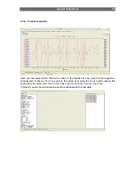
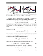
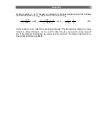
Phase shift of the overall luminescence (
Φ
m), the reference (
Φ
ref) and the indicator (
Φ
ind).
Fluorescence of the indicator in (A) absence and (B) presence of the analyte.
Equations 5 and 6 show the superposition of the phase signals of the reference dye,
which possess a constant decay time and luminescence intensity, and the indicator:
ind
ind
ref
ref
m
m
cos
A
cos
A
cos
A
Φ
⋅
+
Φ
⋅
=
Φ
⋅
(
5
)
ind
ind
ref
ref
m
m
sin
A
sin
A
sin
A
Φ
⋅
+
Φ
⋅
=
Φ
⋅
(
6
)
where A is the amplitude of either overall signal (m), luminophore (ref), or indicator (ind), and
Φ
is the phase angle of either the overall signal (m), the luminophore (ref), or the indicator
(ind), respectively. In case the modulation frequency (f
mod
) is optimal, tan
Φ
ref
is described by
equation 7
1
f
2
tan
ref
mod
ref
=
⋅
⋅
=
Φ
τ
π
(
7
)
and
Φ
ind
can be written as
ref
ind
ref
ind
ind
ind
f
τ
τ
τ
π
τ
π
τ
π
=
⋅
⋅
=
⋅
⋅
=
Φ
2
2
2
tan
mod
(
8
)
The reference luminophore has a decay time that is orders of magnitude longer than that of
the indicator. Consequently,
Φ
ind
can be set equal to zero in equation 9, since at low
modulation frequencies (in the kHz range) there is no phase shift.
0
0
tan
ind
ref
ind
ind
ref
ind
→
Φ
⇒
⎯
⎯
⎯
→
⎯
τ
τ
=
Φ
τ
<<
τ
(
9
)
The decay time of the reference luminophore is not affected by the analyte, hence:
Φ
ref
= constant
Î
tan
Φ
ref
= constant
Î
Φ
ref
= constant
(
10
)
Therefore, equations 5 and 6 can be simplified to give 11 and 12, respectively:
ind
ref
ref
m
m
A
cos
A
cos
A
+
Φ
⋅
=
Φ
⋅
(
11
)
ref
ref
m
m
sin
A
sin
A
Φ
⋅
=
Φ
⋅
(
12
)