
OSS212-D4 Enclosure Quick Guide
For more information please visit our website at
www.Premioinc.com
Copyright © 2017, Premio Inc. All rights reserved.
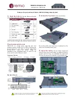
5.
Install Motherboard Components
(CPU,
heatsink, memory) using the guidelines below. For further
details, refer to the motherboard TPS.
Asrock
EP2C612D16C-4L
·
Two LGA2011 (Socket R3)
processor sockets
·
One or two Intel Xeon E5-2600/
4600 &v3 series CPU
·
Intel C612 chipset
·
16 DIMM slots, Quad channel
·
Supports DDR4 2133/1866/1600
·
RDIMM and LRDIMM
·
32GB, 16GB, 8GB, 4GB RDIMM;
64GB, 32GB LRDIMM
·
PCIE1 (x8), PCIE2 (x16/x8 if PCIE1
is populated) connected to CPU1
·
PCIE3 (x8), PCIE4 (x16/x8 if PCIE3
is populated), PCI6 (x16) to CPU2
X16 / x8
x8
x16
x8
X16 / x8
6.
Remove the Inner Rail
from the slide rail.
1
–
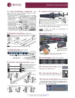
2 Pull the inner rails out. Pull the blue release tab when it hits a stop.
3
–
4 Keep extending inner rail and pull the white detach tab
when it hits the second stop
5
–
6 Unretract the mid rail by pulling the latch on the mid rail
1
2
3
4
5
6
7.
Install Inner Rails
to the enclosure.
Yellow circles are for standoff screws
Secure inner rail with
M4x4L screw (red)
To remove Inner rail from unit:
Pull the latch outward and remove
the keyhole from standoff
8.
Install the Outer Rails to the Rack
as follows:
Red rectangles are locations for slide
rail position (front and rear posts)
Yellow circles are location for
enclosure screws (front only)
1U
2U
Rear Bracket
Front Bracket
1
–
2 Snap the rear part of slide rail
to rear posts
3
–
4 Snap the front part of slide rail
to front posts
1
2
3
4
To remove slide rails, use the latches to undo the assembly as follows:
Rear Bracket
Front Bracket
9.
Install the Unit to the Rack
as follows:
For a complete instruction on how to install unit to the rack,
please follow the Slide Rail Installation Guide.
At least two people are recommended for
mounting process.
10.
Install 2
.5”
Drives
to the enclosure as illustrated:
11.
Drive Mapping
of OSS212-D4 is as follows:
12.
Plug in the Power Cords
to the AC
receptacles on the back of the unit.
13.
Press the Power Button
on the
front of the unit and for the system to boot up.
14.
Access the Serial Console
(when necessary) by
connecting a serial audio cable to the one of the console
ports. Use a terminal console with baud set 38400, 8, N, 1, N.
T
ype “help –a” for
a list of commands.


