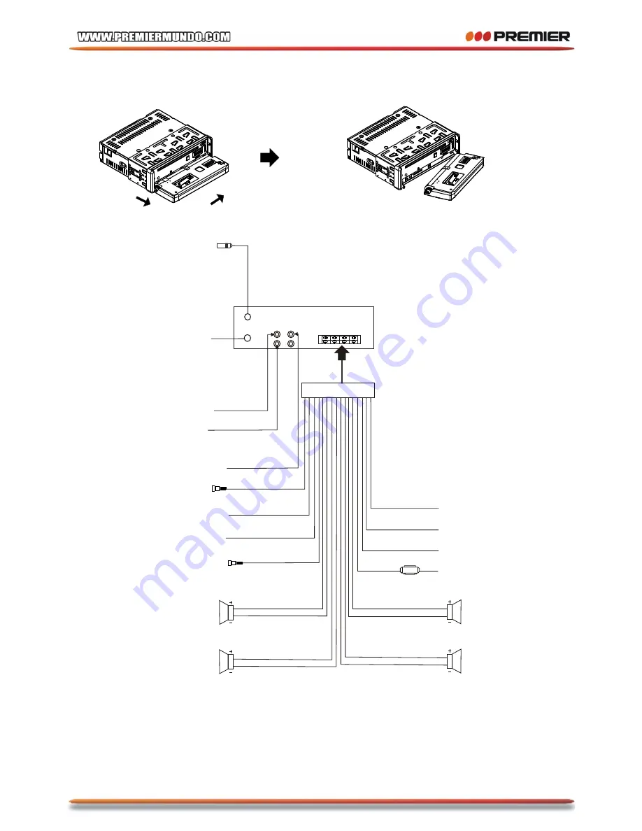
B. Hold the left end of the control panel to slide rightwards a little and pull it towards
you to remove it .
2) Connecting all wires according ot the wiring diagram as follows:
1
2
WIRING DIAGRAM
NOTE:
1. Must use 4 ohms impedance of speakers.
2. After connecting parking Line, video on screen of control panel
will be displayed only after
3. Before finishing wiring, do not attach control panel onto chassis.
applying parking brake.
IGNITION SWITCH
RED
WHITE
WHITE/BLACK
GREY
GREY/BLACK
GREEN
GREEN/BLACK
VIOLET
VIOLET/BLACK
YELLOW
CONSTANT 12 VOLTS
BLACK
GROUND(B-)
BLUE
AUTO ANTENNA
FRONT
Lch SPK.
REAR
Lch SPK.
FRONT
Rch SPK.
REAR
Rch SPK.
BROWN
(B-) PARKING BRAKE
PINK
RADIO ANTENNA JACK
(B+) 12V
REAR
CAMERA
SWITCH
REAR CAMERA INPUT
YELLOW
GREY
SUB WOOFER
AUDIO R OUT (red)
AUDIO L OUT (white)
VIDEO OUTPUT (brown)
FUSE
TV ANTENNA IN
P-5
Summary of Contents for SCR-4710TVD
Page 39: ...P 38 ...
Page 40: ...P 39 ...
Page 41: ...P 40 ...
Page 42: ...P 41 ...
Page 45: ...P 44 ...
Page 46: ...P 45 ...
Page 47: ...P 46 ...
Page 48: ...P 47 ...
Page 49: ...P 48 ...
Page 50: ...P 49 ...
Page 51: ...P 50 ...
Page 52: ...P 51 ...
Page 53: ...P 52 ...
Page 54: ...P 53 ...
Page 55: ...P 54 ...
Page 56: ...P 55 ...
Page 57: ...P 56 ...
Page 58: ...P 57 ...
Page 59: ...P 58 ...
Page 60: ...P 59 ...
Page 61: ...P 60 ...
Page 62: ...P 61 ...
Page 63: ...P 62 ...
Page 64: ...P 63 ...


