background image

+1.866.977.7326 

www.preco.com 

3700076F 

Copyright 2016 

Page 2


Installation: 

Installation  of  the  system  requires  up  to  three  electrical  connections  – 
ignition  power,  ground,  and/or  reverse.    The  reverse  connection  can  be 
skipped if it cannot be found in the cab as the display can be configured to 
receive  the  reverse  signal  from  the  sensor.  However,  it  is  suggested  for 
optimum performance that the display be directly connected to reverse. 
 
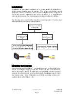
The first step is to determine the machine cab wiring option.  The flow chart 
below details the two display wiring options. 


Connections available 

in vehicle cab

Ignition Power and 

Reverse

Connect display 

Yellow wire to Ignition

Connect display 

Brown wire to Reverse

Connect display 

Orange wire to Ground

Ignition Power only

Connect display 

Yellow wire to Ignition

Connect display 

Orange wire to Ground

“A”

“B”


Mounting the Display: 

Using the supplied  RAM Mount™  components, select the best spot in the 
cab for  mounting the display.  Since the  display has  the Touch to Silence 
feature, the display should be within arm’s length of the machine operator.  
A typical mounting location is on the dash where the display doesn’t inhibit 
the  drivers’  view.   More  information  and  other  mounting  options  are 
available at www.RamMount.com. 


Summary of Contents for PreView WD7102

Page 1: ...PreView Wireless Display WD7102 Operating Manual www preco com...

Page 2: ......

Page 3: ......

Page 4: ......

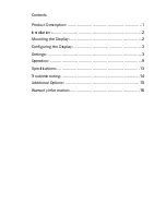
Page 5: ...Contents Product Description 1 Installation 2 Mounting the Display 2 Configuring the Display 3 Settings 3 Operation 9 Specifications 13 Troubleshooting 14 Additional Options 15 Warranty Information 16...

Page 6: ...ules These limits are designed to provide reasonable protection against harmful interference in a residential installation This equipment generates uses and can radiate radio frequency energy and if n...

Page 7: ...tures a unique Touch to Silence feature that allows the operator to acknowledge and silence the audible alert simply by touching anywhere on the screen Although the communication between the WD7102 an...

Page 8: ...the two display wiring options Connections available in vehicle cab Ignition Power and Reverse Connect display Yellow wire to Ignition Connect display Brown wire to Reverse Connect display Orange wire...

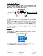
Page 9: ...he firmware boot loader audio file revisions the display s serial number and a short functional description of the system To view the system settings and configure the system press the icon To return...

Page 10: ...should be set where the display alerts can be heard above all in cab noises Max volume is approximately 105dB 10CM There are four different audible alerts available for use Press the Next button to c...

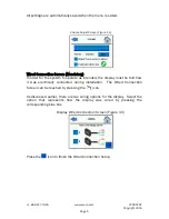
Page 11: ...ate as intended the display must be told how it was electrically connected during installation The Wired Connection Screen can be reached by pressing the icon As discussed earlier there are two wiring...

Page 12: ...e screen shot below Wireless Connect Screen Figure 1 6 Press on the blue box containing the desired sensor serial number to connect to that sensor After 2 3 seconds the display should connect to the s...

Page 13: ...l can t find it or is having trouble connecting please see the Troubleshooting section of this manual Wireless Connect Screen 3 Figure 1 8 Change Passcode Screen Optional The Change Passcode screen is...

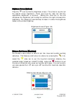
Page 14: ...tomatically increase or reduce the brightness based on the ambient lighting Brightness Screen Figure 1 9 Distance Alert Screen Mandatory The Distance Alert screen is used to set the visual and audible...

Page 15: ...the system is not active Figure 2 1 Home Screen Generic Figure 2 1 A couple seconds after power up the PRECO Electronics logo will change to an image depicting a truck that is not reversing Figure 2...

Page 16: ...ll be replaced by a yellow triangle Figure 3 2 The audible alert will begin to sound to notify you that an object has been detected Touch to Silence will be visible on the screen unless it has been di...

Page 17: ...gain until the detection clears The Home screen can be reached while the Active screen is displayed by executing a long press on the screen After pressing the screen for at least 1 second the message...

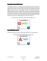
Page 18: ...wired only to ignition was used and the sensor does not communicate with the display the display will continue to show the Not In Reverse message Figure 2 2 as it relies on the sensor to tell the dis...

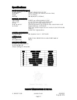
Page 19: ...ree 26 AWG wires connect to ignition and or reverse lamp circuit Aux Output Single 26 AWG wire 33V tolerant Active State switched to ground over current protected to 125mA sink maximum Inactive State...

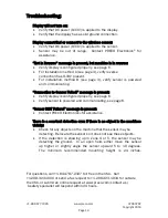
Page 20: ...ssage is present Verify display is configured properly see page 6 Verify sensor is powered and communicating see page 6 Sensor BIST Failure message is present Contact PRECO Electronics for assistance...

Page 21: ...t 2016 Page 15 Additional Options Custom System Configurations Thanks to the advanced engineering by the PRECO Electronics Engineers the technology behind PreView sensors can easily integrate or contr...

Page 22: ...TICULAR PURPOSE ARE HEREBY EXCLUDED AND SHALL NOT APPLY TO THE PRODUCT BUYER S SOLE AND EXCLUSIVE REMEDY IN CONTRACT TORT OR UNDER ANY OTHER THEORY AGAINST MANUFACTURER RESPECTING THE PRODUCT AND ITS...

Page 23: ......
Page 24: ...Proudly developed by 10335 W Emerald St Boise Idaho 83704 www preco com 1 866 977 7326 3700076F...

Reviews: