


ProtEX-MAX PD8-6210 Explosion-Proof Analog Input Batch Controller
Instruction Manual
29
Signal Connections
Signal connections are made to a six-terminal
connector labeled SIGNAL. The COM (common)
terminal is the return for the 4-20 mA and the
10 V
input signals.
Current and Voltage Connections
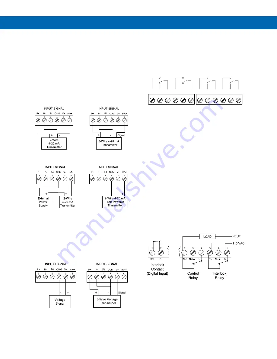
The following figures show examples of current and
voltage connections.
There are no switches or jumpers to set up for current
and voltage inputs. Setup and programming is
performed through the programming buttons or
MeterView Pro software.
Figure 8. Transmitter Powered by Internal Supply
Figure 9. Transmitter Powered by Ext. Supply
or Self-Powered
The current input is protected against current
overload by a resettable fuse. The display may or
may not show a fault condition depending on the
nature of the overload.
The fuse limits the current to a safe level when it
detects a fault condition, and automatically resets
itself when the fault condition is removed.
Figure 10. Voltage Input Connections
The controller is capable of accepting any voltage from
-10 VDC to +10 VDC.
Relay Connections
Relay connections are made to two six-terminal
connectors labeled RELAY1
– RELAY4. Each relay’s
C terminal is common only to the normally open (NO)
and normally closed (NC) contacts of the
corresponding relay. The relays’ C terminals should
not be confused with the COM (common) terminal of
the INPUT SIGNAL connector.
Figure 11. Relay Connections
Interlock Relay Feature
As the name implies, the interlock relay feature
reassigns one, or more, alarm/control relays for use
as interlock relay(s). Interlock contact(s) are wired to
digital input(s) and activate the interlock relay. This
feature is enabled by configuring the relay, and the
corresponding digital input(s), see
Interlock Relay (Force On) Feature
on page
In the example below, an Interlock Contact switch is
connected to a digital input, which will be used to
force on (energize) the Interlock Relay. The Interlock
Relay and the Control Relay are connected in series
with the load.
•
When the Interlock Contact is closed (safe), the
Interlock Relay energizes, allowing power to flow
to the Control Relay; the corresponding front
panel LED is on.
•
When the Interlock Contact is open, the
corresponding front panel LED flashes (locked
out), the Interlock Relay is de-energized,
preventing power from flowing to the Control
Relay and the load.
Figure 12. Interlock Connection
C
NO
NO
NC
NC
C
RELAY4
RELAY3
4
3
6
5
2
1
C
NO
NO
NC
NC
C
RELAY2
RELAY1
4
3
6
5
2
1


