background image

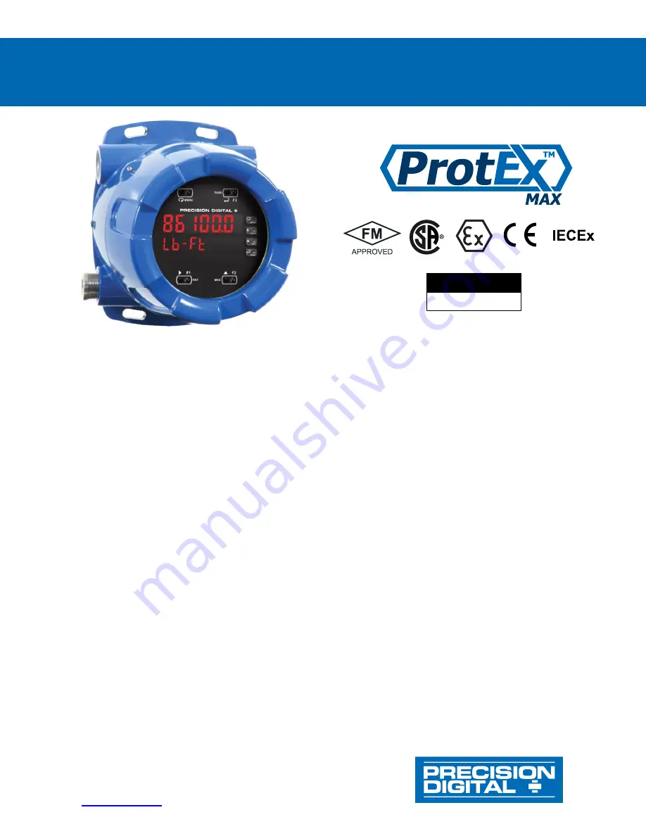
PD8-6100 Strain Gauge, Load Cell, and mV Meter 

Instruction Manual


PRECISION DIGITAL CORPORATION


233 South Street • Hopkinton MA 01748 USA 
Tel (800) 343-

1001 • Fax (508) 655-8990 

www.predig.com


Fully-Approved Explosion-Proof Meter 


15, 30, 150, 300 mV unipolar; ±15, ±25, ±150, ±250 mV bipolar Inputs 


Dual-Line 6-Digit Display, 0.6" (15 mm) & 0.46" (12 mm) 


Selectable 5 or 10 VDC Sensor Excitation @ 25 mA Max 


SafeTouch Through-Glass Button Programming 


Display Mountable at 0°, 90°, 180°, & 270°  


4 Relays with Interlocking Capa Isolated 4-20 mA Output Option 


Free PC-Based, On-Board, MeterView Pro USB Programming Software 


SunBright Display Standard Feature; Great for Outdoor Applications 


Operating Temperature Range: -40 to 60°C (-40 to 140°F) 


FM Approved as Explosion-Proof / Dust-Ignition-Proof / Flame-Proof 


CSA Certified as Explosion-Proof / Dust-Ignition-Proof / Flame-Proof 


ATEX and IECEx Certified as Flame-Proof 


Input Power Options: 85-265 VAC / 90-265 VDC or 12-24 VDC / 12-24 VAC 


Supports One (1) 350 

Ω Load Cell 


Capture or Programmable Tare Feature 


Auto-Zero Feature Eliminates Zero Drift 


Ratiometric Operation 


Programmable Display, Function Keys & Digital Inputs 


Flanges for Wall or Pipe Mounting 


Explosion-Proof, IP68, NEMA 4X Die-Cast Aluminum Enclosure 


On-Board RS-485 Serial Communications 


Modbus RTU Communication Protocol Standard 


Password Protection 


Four 3/4" NPT Threaded Conduit Openings (Two Plugs Installed) 


Pipe Mounting Kits 


Stainless Steel Tag Available 


3-Year Warranty


MeterView Pro 

USB Install 

Summary of Contents for ProtEX-MAX PD8-6100

Page 1: ...r Outdoor Applications Operating Temperature Range 40 to 60 C 40 to 140 F FM Approved as Explosion Proof Dust Ignition Proof Flame Proof CSA Certified as Explosion Proof Dust Ignition Proof Flame Proof ATEX and IECEx Certified as Flame Proof Input Power Options 85 265 VAC 90 265 VDC or 12 24 VDC 12 24 VAC Supports One 1 350 Ω Load Cell Capture or Programmable Tare Feature Auto Zero Feature Elimina...

Page 2: ...2 ...

Page 3: ...of the defective unit See Warranty Information and Terms Conditions on www predig com for complete details Registered Trademarks All trademarks mentioned in this document are the property of their respective owners 2022 Precision Digital Corporation All rights reserved FREE MeterView Pro Programming Software The meter can be powered from the USB connection When using the USB connection DO NOT appl...

Page 4: ...ower Connections 24 Signal Connections 25 Switch Configuration 25 Shunt Calibration 27 Relay Connections 27 Interlock Relay Feature 27 Switching Inductive Loads 28 RS 485 Connections 28 RS 485 Multi Drop Connection 28 F4 Digital Input Connections 29 4 20 mA Output Connections 29 Analog Output Power Supply 29 Remote Programming 29 Setup and Programming 30 Overview 30 LED Status Indicators 30 Progra...

Page 5: ... 48 Reset Menu reset 48 Tare Menu Tare 48 Tare Functionality tare 48 Manual Control Menu Contrl 48 Setting Up the Password pass 49 Protecting or Locking the Meter 49 Making Changes to a Password Protected Meter 49 Disabling Password Protection 49 Advanced Features Menu 50 Advanced Features Menu Display Messages 50 Noise Filter filter 51 Noise Filter Bypass bypass 51 Rounding Feature round 51 Modbu...

Page 6: ...iguration Switch 25 Figure 9 Strain Gauge Powered by Internal Supply 26 Figure 10 Strain Gauge Powered by External Supply 26 Figure 11 mV Transducer Input Connections 26 Figure 12 Four wire mV Transducer Connections 26 Figure 13 Shunt Resistor 27 Figure 14 Relay Connections 27 Figure 15 Interlock Connections 27 Figure 16 AC and DC Loads Protection 28 Figure 17 Low Voltage DC Loads Protection 28 Fi...

Page 7: ...cations The 4 20 mA isolated output Modbus RTU serial communications and digital I O features make the ProtEX MAX an excellent addition to any system SafeTouch Buttons To make it possible to program and operate the ProtEX MAX in a hazardous area the programming buttons that are located behind the glass window can be operated without removing the cover by using the SafeTouch through glass buttons T...

Page 8: ...plete line of ProtEX MAX products predig com videos ProtEXMAX_Overview MeterView Pro Programming Software Learn how easy it is to program the ProVu ProtEX MAX process meter using MeterView Pro software predig com videos MVPro_SW MeterView Pro Software Demonstration Learn how easy it is to program Precision Digital s ProVu ProtEX MAX process meter for a level application using MeterView Pro PC base...

Page 9: ... not only saves the cost of an external power supply but also greatly simplifies wiring In addition there is a second 24 VDC 25 mA power supply provided with the 4 20 mA output option The first thing you notice about the PD8 6100 is its modern looking rugged die cast aluminum housing with convenient mounting flanges Housed inside this enclosure is a dual line 6 digit display with high intensity LE...

Page 10: ...ay In the case where there has been drift in the strain gauge output over time zero is used to eliminate this drift and provide a true zero reading For example if an empty scale were to display a value other than zero the zero function would tell the meter to show zero regardless of the current input signal Capture Tare The tare function also zeroes out the display In the case of scale weight tare...

Page 11: ...t 2 and displaying the default value of 100 mV The 0 is brighter than the rest of the digits indicating that it is the number that will be changed by the Up arrow The ProtEX MAX is now prompting for what the user wants Display 2 to be that is the value that corresponds to 100 mV In this case Display 2 is currently set to 100 00 Dual Scale Display Feature The ProtEX MAX PD8 6100 has a rather unique...

Page 12: ... programmed and operated without removing the cover and exposing the electronics in a hazardous area These buttons can be disabled for security by selecting the DISABLE setting on the NO CONTACT BUTTONS switch located on the back of the electronics module inside the enclosure Rugged Heavy Duty Enclosure The ProtEX MAX is housed in a rugged NEMA 4X 7 9 IP68 die cast aluminum enclosure designed to w...

Page 13: ...ess steel wire and lead seal for easy mounting wherever you need it Removable Screw Terminals Industrial applications require screw terminal connections for easy field wiring and the ProtEX MAX goes one step further in convenience by also making them removable Note The above photograph is representative of the back of the PD8 6100 in every regard except for the signal input connector See PROVU Ele...

Page 14: ...ettings are stored in non volatile memory for a minimum of ten years if power is lost Power Options 85 265VAC50 60Hz 90 265VDC 20Wmax 12 24 VDC 12 24 VAC 15 W max Powered over USB for configuration only Fuse Required external fuse UL Recognized 5 A max slow blow up to 6 meters may share one 5 A fuse Normal Mode Rejection Greater than 60 dB at 50 60 Hz Isolation 4 kV input to power line 500 V input...

Page 15: ...esistive load 1 14 HP 50 W 125 250 VAC for inductive loads Noise Suppression Noise suppression is recommended for each relay contact switching inductive loads see Switching Inductive Loads on page 27 for details Deadband 0 100 of span user programmable High or Low Alarm User may program any alarm for high or low trip point Unused alarm LEDs and relays may be disabled turn off Relay Operation Autom...

Page 16: ...Max Distance 3 937 1 200 m max Status Indication Separate LEDs for Power METER LINK Transmit TX and Receive RX Modbus RTU Serial Communications Slave ID 1 247 Meter address Baud Rate 300 19 200 bps Transmit Time Delay Programmable between 0 and 199 ms Data 8 bit 1 start bit 1 or 2 stop bits Parity Even Odd or None with 1 or 2 stop bits Byte to Byte Timeout 0 01 2 54 second Turn Around Delay Less t...

Page 17: ...b T5 T6 Zone 21 AEx tb IIIC T90 C Ta 40 C to 65 C T6 Ta 40 C to 60 C T5 Ta 40 C to 65 C Certificate Number 3047283 CSA Class I Division 1 Groups B C D Class II Division 1 Groups E F G Class III Division 1 Class I Zone 1 Ex d IIC Zone 21 Ex tb IIIC T90 C 40 C Tamb 60 C Temperature Code T6 40 C Tamb 65 C Temperature Code T5 Enclosure Type 4X IP68 Certificate Number 2531731 ATEX II 2 G D Ex d IIC T G...

Page 18: ...ed by opening the enclosure To access electrical connectors remove the 2 captive screws and then remove the electronics module Connectors are on the rear of the electronics module Unpacking Remove the meter from box Inspect the packaging and contents for damage Report damages if any to the carrier If any part is missing or the meter malfunctions please contact your supplier or the factory for assi...

Page 19: ... holes located in the cast in flanges In addition the internal electronic assembly can be rotated to allow the enclosure to be mounted in any position To mount the meter to a wall follow these instructions Prepare a section of wall approximately 7 x 8 5 178 mm x 216 mm for meter mounting by marking with a pencil the mounting holes shown in Figure 1 on the wall Select the appropriate mounting screw...

Page 20: ...This kit includes two U bolts the necessary hardware and is available in zinc plated steel PDA6848 and 316 stainless steel PDA6848 SS To mount the meter using a U Bolt kit follow these instructions Orient the groove on the back of the instrument with the pipe and secure it to the pipe with the two U bolts and hardware provided Vertical Pipe Mounting Horizontal Pipe Mounting ...

Page 21: ... meter and the other end to the computer The computer will automatically install the driver software it needs to talk to the meter Follow the on screen instructions and allow sufficient time for the process to complete This can take a few minutes If the process is interrupted then it could leave the system in an unstable condition Only one meter may be connected at a time Attaching multiple meters...

Page 22: ...ccordance with all agency requirements and applicable national state and local codes to prevent damage to the meter and ensure personnel safety Static electricity can damage sensitive components Observe safe handling precautions for static sensitive components Use proper grounding procedures codes If the instrument is installed in a high voltage environment and a fault or installation error occurs...

Page 23: ...H7 and PD8 6100 7H7 Figure 5 PROVU Electronics Module Layout USB Connection Figure 6 USB Connection DO NOT disconnect the RJ45 M LINK connector cable Otherwise the instrument will not function properly When using the USB connection the meter should only be connected to a computer when both devices are in a non hazardous area ...

Page 24: ...onnector labeled POWER The meter will operate regardless of DC polarity connection The and symbols are only a suggested wiring convention There are separate models for low voltage and high voltage power See Ordering Information on page 7 for details Figure 7 Power Connections AC or DC POWER Required External Fuse 5 A max 250 V Slow Blow POWER ...

Page 25: ...he internal circuitry Narrower ranges require more amplification OFF Range Lower internal gain Turn this switch OFF for the following input ranges 150 300 150 or 250 mV ON Range Higher internal gain Turn this switch ON for the following input ranges 15 30 15 or 25 mV Polarity Switch 3 The polarity switch selects whether the range is unipolar and starts at zero i e 0 to 30 mV or bipolar and starts ...

Page 26: ...stor is connected to the input bridge Turn switch ON when you want to simulate a strain load Strain Gauge Connections The following figures show examples of strain gauge connections There is a 5 position DIP switch CONFIG to set up the input ranges and sensor excitation Note Refer to Switch Configuration on page 25 for proper configuration switch positioning Figure 9 Strain Gauge Powered by Intern...

Page 27: ...the COM common terminal of the INPUT SIGNAL connector Figure 14 Relay Connections Interlock Relay Feature As the name implies the interlock relay feature reassigns one or more alarm control relays for use as interlock relay s Interlock contact s are wired to digital input s and activate the interlock relay This feature is enabled by configuring the relay and the corresponding digital input s see S...

Page 28: ...ng an inductive load Part number PDX6901 Note Relays are de rated to 1 14th HP 50 watts with an inductive load RS 485 Connections The RS 485 connections are made to a five terminal connector used for Modbus RTU serial communications The RS 485 terminals include Transmit Data DO and DO Receive Data DI and DI and Signal Ground See Modbus RTU Serial Communications serial on page 51 for more informati...

Page 29: ...ally open contact across F4 and COM or with an active low signal applied to F4 It can be used to operate the tare function for remote operation of front panel buttons to acknowledge reset relays or to reset max min values See Function Keys Digital I O Available Settings on page 54 for a complete list of capabilities Figure 20 F4 Digital Input Connections 4 20 mA Output Connections Connections for ...

Page 30: ...e control module to set the meter input selection See Switch Configuration on page 25 to setup the switch Setup and programming is done using MeterView Pro or through the programming buttons After power and input signal connections have been completed and verified apply power to the meter LED Status Indicators LED State Indication 1 4 Steady Alarm condition based on set and reset points independen...

Page 31: ...nector board To actuate a button press one finger to the glass directly over the marked button area Then retract finger more than three inches from the glass before pressing the next button When the cover is removed the four mechanical buttons located next to the sensors are used The sensors are disabled when a mechanical button is pressed and will automatically be re enabled after 60 seconds of i...

Page 32: ...u SCAL 1 Scale 1 Enter the Scale menu for PV1 SCAL 2 Scale 2 Enter the Scale menu for PV2 Display Functions Messages Display Parameter Action Setting Description Cal Calibrate Enter the Calibration menu Inp 1 Input 1 Calibrate input 1 signal or program input 1 value Dis 1 Display 1 Program display 1 value Inp 2 Input 2 Calibrate input 2 signal or program input 2 value up to 32 points Dis 2 Display...

Page 33: ...ss Enter to reset min display Rst HL Reset high low Press Enter to reset max min displays Rst tr Reset tare Press Enter to reset tare tare Tare Enter Tare menu Captur Capture Press Enter to set meter to capture tare using the Tare button Prog T Programm able Press Enter to set meter to programmable tare and enter a value Off Off Press Enter to disable the tare function Contrl Control Enter Manual ...

Page 34: ...it and Up arrow to increment digit value The digit being changed is displayed brighter than the rest Press and hold up arrow to auto increment the display value Press the Enter button at any time to accept a setting or Menu button to exit without saving changes Setting Up the Meter setup The Setup menu is used to select 1 Unipolar e g 0 30 mV or bipolar e g 25 mV polarity input range ratiometric o...

Page 35: ...n menu Setting the Display Units units Enter the pre defined engineering unit or custom unit The pre defined units have automatic conversion factors This unit will be displayed if d unit is selected as the lower display parameter See Setting the Display Parameter Intensity dsplay flow chart on page 39 to access the display menu to show the unit on the lower display The custom unit may also be used...

Page 36: ...imal point at all Pressing the Right arrow moves the decimal point one place to the right until no decimal point is displayed and then it moves to the leftmost position Pressing the Up arrow moves the decimal point to the left If the dual scale feature is selected the decimal point selections for PV1 PV2 are enabled Programming the Meter prog The meter may either be scaled SCALE without applying a...

Page 37: ...up the meter for at least 15 minutes before performing calibration to ensure specified accuracy Multi Point Calibration Scaling The meter is set up at the factory for 2 point linear calibration The number of points for multi point calibration scaling is set up in the Advanced Features menu Up to 32 linearization points may be selected for PV1 and up to 8 linearization points may be selected for PV...

Page 38: ...the error message is displayed the meter reverts to input 2 during calibration or scaling and to input 1 during internal calibration allowing the appropriate input signal to be applied or programmed The error message might be caused by any of the following conditions 1 Input signal is not connected to the proper terminals or it is connected backwards 2 Wrong signal selection in Setup menu 3 Minimu...

Page 39: ...t and display press the Menu button to exit programming and skip the rest of the setup menu Press the Menu button again and the Up arrow to reach the Program menu and complete the scaling or calibration of the meter Display Intensity d Inty The meter has eight display intensity levels to give the best performance under various lighting conditions Select intensity 8 for outdoor applications The def...

Page 40: ...d time g Off relay state controlled by Interlock feature 2 Set point 3 Reset point 4 Fail safe operation a On enabled b Off disabled 5 Time delay a On delay 0 999 9 seconds b Off delay 0 999 9 seconds Setting the Relay Action Operation of the relays is programmed in the Action menu The relays may be set up for any of the following modes of operation 1 Automatic reset non latching 2 Automatic manua...

Page 41: ...thin safe limits and the relay coil is de energized when the alarm condition exists The fail safe operation is set independently for each relay Select on to enable or select off to disable fail safe operation Programming Time Delay The On and Off time delays may be programmed for each relay between 0 and 999 9 seconds The relays will transfer only after the condition has been maintained for the co...

Page 42: ... Relay coil is energized in non alarm condition In case of power failure relay will go to alarm state Time Delay Operation The following graphs show the operation of the time delay function When the signal crosses the set point the On time delay timer starts and the relay trips when the time delay has elapsed If the signal drops below the set point high alarm before the time delay has elapsed the ...

Page 43: ...mpling Operation When the signal crosses the set point the relay trips and the sample time starts After the sample time has elapsed the relay resets The cycle repeats every time the set point is crossed going up for high alarms and going down for low alarms The sample time can be programmed between 0 1 and 5999 9 seconds ...

Page 44: ... status indication for the following LED Status 1 Alarm 1 2 Alarm 2 3 Alarm 3 4 Alarm 4 The meter is supplied with four alarm points that include front panel LEDs to indicate alarm conditions This standard feature is particularly useful for alarm applications that require visual only indication The LEDs are controlled by the set and reset points programmed by the user When the display reaches a se...

Page 45: ... Off Off Latching Relay LatcH In this application the meter is set up for manual reset at any time Acknowledging the alarm even if the alarm condition is still present resets the relay and turns off the LED Manual reset any time Condition LED Relay Normal Off Off Alarm On On Ack Off Off Latching Relay with Clear Lt Clr In this application the meter is set up for manual reset only after the signal ...

Page 46: ...g Relay Set Point Reset Point Function 1 30 000 10 000 Controls pump 1 2 35 000 5 000 Controls pump 2 3 4 000 9 000 Controls low alarm 4 40 000 29 000 Controls high alarm Pump Alternation Operation 1 Pump 1 turns on when level reaches 30 000 when level drops below 10 000 pump 1 turns off 2 The next time level reaches 30 000 pump 2 turns on when level drops below 10 000 pump 2 turns off 3 If the le...

Page 47: ...tup Relay Action menu and set the action to off 2 In the Advanced features User menu program any of the digital inputs to Force On any of the internal relays 1 4 3 Connect a switch or dry contact between the 5V terminal and the corresponding digital input dI 1 to dI 4 terminal Interlock Relay Operation Example Relays 1 2 are configured to energize their front panel LEDs are steady on when SW1 SW2 ...

Page 48: ...to select the tare mode There are three modes of operation Capture Tare Programmable Tare and Off Capture Tare Pressing the Tare key zeroes the display and the T indicator flashes indicating that tare is applied to the reading e g Net weight Programmable Tare Program a known value to be subtracted from the display value to obtain the net value Pressing Reset tare clears the tare value to zero Prog...

Page 49: ...utton is pressed Press the Enter button while the message is being displayed and enter the correct password to gain access to the menu After exiting the programming mode the meter returns to its password protected condition Disabling Password Protection To disable the password protection access the Password menu and enter the correct password twice as shown below The meter is now unprotected until...

Page 50: ...ation Advanced Features Menu Display Messages Display Parameter Action Setting SCALE Scale Scaling parameter SCAL 1 Scale 1 Scaling parameter 1 SCAL 2 Scale 2 Scaling parameter 2 CutofF Cutoff Set low value cutoff Auto 0 Auto Zero Enter the Auto Zero function on off AoutPr Analog output programming Program analog output parameters Source Source Select source for the 4 20 mA output O rang Overrange...

Page 51: ...e filter bypass may be set between 0 1 and 99 9 of full scale Rounding Feature round The rounding feature is used to give the user a steadier display with fluctuating signals Rounding is used in addition to the filter function Rounding causes the display to round to the nearest value according to the rounding selected See examples below Rounding Selection Actual Value Display Value Actual Value Di...

Page 52: ...n be programmed with up to 8 linearization points Auto Zero Auto 0 Auto zero corrects for drift that can occur over time that causes the input signal to slowly change The meter will continue to read zero despite slow and small changes to the input signal The auto zero value represents the percent of full scale drift that the meter will correct Under normal circumstances when the signal increases q...

Page 53: ...ed to use a milliamp meter with a resolution of at least 0 1 µA to measure the output current The values saved internally during this procedure are used for scaling the 4 20 mA output in the Setup menu Analog Output Calibration Procedure 1 Wire the PD8 6100 4 20 mA output to a current loop that includes a power supply internal or external 12 to 24 VDC and the mA input on the digital meter See Figu...

Page 54: ...nction as they have been programmed O Hold Hold current relay states and analog output as they are until a button assigned to enable relays Rly E is pressed d Hold Hold the current display value relay states and analog output momentarily while the function key or digital input is active The process value will continue to be calculated in the background Ln1 Hi Display minimum display value on line ...

Page 55: ... low input signal e g 0 00 mV and press Enter The display flashes for a moment while the meter is accepting the low input signal 5 After the display stops flashing a number is displayed with the leftmost digit brighter than the rest The bright digit is the active digit that can be changed by pressing the Up arrow button Press the Right arrow button to move to the next digit 6 Set the display value...

Page 56: ...menu To learn more about SafeTouch buttons see this video predig com videos Safetouch_Buttons SafeTouch Buttons The ProtEX MAX is equipped with four sensors that operate as through glass buttons so that it can be programmed and operated without removing the cover and exposing the electronics in a hazardous area These buttons can be disabled for security by selecting DISABLE on the switch labeled N...

Page 57: ...e Function Keys User Menu user on page 54 for details Maximum Minimum Readings The max min readings peak valley reached by the process can be displayed either continuously or momentary 1 Display briefly by assigning to the F1 F3 function keys or to the digital inputs in the User menu Any of the F1 F3 function keys buttons and the digital inputs can be programmed to reset the max min readings 2 Dis...

Page 58: ...e through all digits decimal points and relay indicators to enable the operator to check that all LEDs are functioning properly 4 Press the Enter button again to access the Information menu info or press the Menu button to return to Run Mode Determining Software Version To determine the software version of a meter 1 Go to the Diagnostics menu diAG and press Enter button 2 Press Up arrow button and...

Page 59: ...0 00 Relay 4 reset point RSt 4 35 00 Fail safe relay 1 Fls 1 Off Fail safe relay 2 Fls 2 Off Fail safe relay 3 Fls 3 Off Fail safe relay 4 Fls 4 Off Parameter Display Default Setting On delay relay 1 On 1 0 0 sec Off delay relay 1 Off 1 0 0 sec On delay relay 2 On 2 0 0 sec Off delay relay 2 Off 2 0 0 sec On delay relay 3 On 3 0 0 sec Off delay relay 3 Off 3 0 0 sec On delay relay 4 On 4 0 0 sec O...

Page 60: ... error message during calibration Error Check 1 Signal connections 2 Input selected in Setup menu 3 Minimum input span requirements Meter displays 1 999999 2 99999 3 fault Check 1 Input selected in Setup menu 2 Signal at Signal connector 3 Input exceeds range selected Display is unstable Check 1 Input signal stability and value 2 Display scaling vs input signal 3 Filter and bypass values increase ...

Page 61: ... and RX are off when trying to communicate Remove all unnecessary cables and instruments from the bus Try getting the system to work with only one device to ease troubleshooting and then expand the system one device at a time Communications slow Increase the baud rate Sensor is not receiving power from PD8 6100 Check and make sure Excitation Switch 1 is set to ON for Internal Excitation See Excita...

Page 62: ...ProtEX MAX PD8 6100 Strain Gauge Load Cell and mV Meter Instruction Manual 62 NOTES ...

Page 63: ......

Page 64: ...655 8990 www predig com LIM8 6100_G SFT071 Ver 4 211 up 07 22 Contact Precision Digital Technical Support Call 800 610 5239 or 508 655 7300 Fax 508 655 8990 Email support predig com Sales Support Call 800 343 1001 or 508 655 7300 Fax 508 655 8990 Email sales predig com Place Orders Email orders predig com For the latest version of this manual please visit www predig com ...

Reviews: