FOTO9S2A
FOTO9S2AST
ENGLISH
ISFT9S2AEU_04_02.doc
4
4. TRIGGER BOX CONNECTION AND START-UP
Before installing the FOTO9S2A photocell amplifier read the “General safety warnings ”.
•
Fix the box by means of the special fixing holes.
•
Align the probes
•
Pass the connection cables through the special slots in the FOTO9S2A version, or the special cable conduits in the
FOTO9S2AST version.
•
Connect the power supply and signal cables. The maximum connection distance between electronics and probes is
20 metres.
N.B.: For connection of the transmitter probes you must connect the central cable (red wire) to the common terminal
TX and the braided wire to terminals 1 or 2. For connection of the receiver probes you must connect the braided wire
to the common terminal RX and the central cable (white wire) to terminals 1 or 2.
•
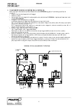
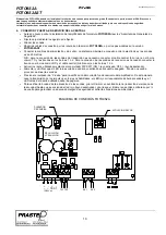
Enable the beams utilised by means of the Dip-Switch SW1 (ON = beam enabled, OFF = beam disabled)
•
Power up and check that the Red LED associated with each enabled beam is off. If this is not the case, align the
probes.
•
Press the “Test” button to verify correct functioning of the amplifier. In this way impulse transmission on the enabled
beams ceases. The corresponding Red LED must light up and the Green LED of the output used must go out.
•
To verify the efficiency of the probe alignment, turn the Trimmer clockwise (reduction of probe range) until a red LED
comes on (beam unaligned), then turn the Trimmer a quarter turn anticlockwise to ensure an adequate safety
margin for variations in environmental conditions.
TEST
BUTTON
BEAM ENABLING
ATTENUATION
ADJUSTMENT
FOTO9S2A CONNECTION DIAGRAM
TX1 TX2
RX1 RX2
+ - + -
~ ~ TEST
12/24Vac


