HRK3-HB-7
V
IA
L
ITE
HD
3U
CHASSIS
H
ANDBOOK
12
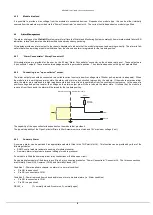
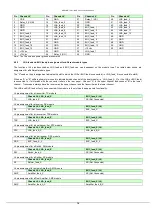
Pin out
– J1 “Alarm Concentrator” connector*
Pin
Chassis J1*
Pin
Chassis J1*
Pin
Chassis J1*
Pin
Chassis J1*
1
GND
14
Analogue_monitor_B_8
27
ALARM_3
40
Analogue_monitor_B_11
2
ALARM_2
15
Analogue_monitor_B_10
28
ALARM_5
41
Analogue_monitor_B_13
3
ALARM_4
16
Analogue_monitor_B_12
29
ALARM_7
42
GND
4
ALARM_6
17
GND
30
ALARM_9
43
GND
5
ALARM_8
18
GND
31
ALARM_11
44
Analogue_monitor_A_2
6
ALARM_10
19
Analogue_monitor_A_1
32
ALARM_13
45
Analogue_monitor_A_4
7
ALARM_12
20
Analogue_monitor_A_3
33
GND
46
Analogue_monitor_A_6
8
ALARM_14
21
Analogue_monitor_A_5
34
ALARM_P_1
47
Analogue_monitor_A_8
9
ALARM_P_2
22
Analogue_monitor_A_7
35
Analogue_monitor_B_1
48
Analogue_monitor_A_10
10
GND
23
Analogue_monitor_A_9
36
Analogue_monitor_B_3
49
Analogue_monitor_A_12
11
Analogue_monitor_B_2
24
Analogue_monitor_A_11
37
Analogue_monitor_B_5
50
GND
12
Analogue_monitor_B_4
25
Analogue_monitor_A_13
38
Analogue_monitor_B_7
13
Analogue_monitor_B_6
26
ALARM_1
39
Analogue_monitor_B_9
Note:
See your module handbooks for assignment and function of the “Analogue_monitor” pins
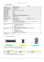
4.9.1
Chassis connector pin out J4 & J19-31
The pin out of connectors J4 & J19-31 has been changed, to add additional functionality to the chassis. Check serial number to find correct
pin out. See section 4.9.1.1 and 4.9.1.2 below. The approximate last shipment date of the early revision racks is July 2013, contact
ViaLite
Communications
for more details.
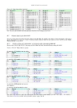
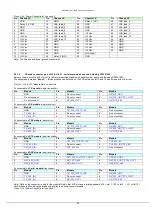
4.9.1.1
Chassis connector pin out J4 & J19-31 - serial numbers below and including SN1221901
Below is the pin out of J4 and J19-J31 for all early production chassis with serial number below and including SN1221901.
Pin Out
– J19 to J31 “Module Data” connectors
If connected to a
TX module
(single transmitter)
Pin
Module
Pin
Module
Pin
Module
1
GND
4
Do not connect
7
RX_422_OUT-
2
Do not connect
5
Do not connect
8
RX_232_OUT [TTL_OUT]*
3
Do not connect
6
RX_
9
RX_RTS_485
If connected to a
RX module
(single receiver)
Pin
Module
Pin
Module
Pin
Module
1
GND
4
TX_232_IN [TTL_IN]*
7
Do not connect
2
TX
5
Do not connect
8
Do not connect
3
TX_422_IN-*
6
Do not connect
9
Do not connect
If connected to a
TRX module
(transceiver)
Pin
Module
Pin
Module
Pin
Module
1
GND
4
TX_232_IN [TTL_IN]*
7
RX_422_OUT-
2
TX
5
Do not connect
8
RX_232_OUT [TTL_OUT]*
3
TX_422_IN-*
6
RX_
9
RX_RTS_485
If connected to a
DTX module
(dual transmitter)
Pin
Module
Pin
Module
Pin
Module
1
GND
4
TX1_232_IN [TTL1_IN]*
7
TX2_422_IN-
2
TX1
5
Do not connect
8
TX2_232_IN [TTL2_IN]*
3
TX1_422_IN-
6
TX2
9
Do not connect
If connected to a
DRX module
(dual receiver)
NOT supported
If connected to a
Serial module
(transceiver)
Pin
Module
Pin
Module
Pin
Module
1
GND
4
TX_232_IN [TTL_IN]*
7
RX_422_OUT-
2
TX
5
Do not connect
8
RX_232_OUT [TTL_OUT]*
3
TX_422_IN-*
6
RX_
9
RX_RTS_485
Note: Data on the connector is only for the module fitted in that 5HP slot and is
printed beneath (J19 = slot 1, J20 = slot 2 … J31 = Slot 13)
Connections in
Blue text
are optional and only available on some types of module


