HRK3-HB-7
V
IA
L
ITE
HD
3U
CHASSIS
H
ANDBOOK
13
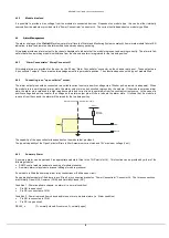
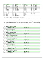
Pin out
– J4 “Power Concentrator” connector*
Pin
Chassis J4*
Pin
Chassis J4*
Pin
Chassis J4*
Pin
Chassis J4*
1
CSB
14
GND
27
Relay_1 (NC)
40
LNA_feed_3
2
Relay_2 (COM)
15
LNA_feed_2
28
GND
41
LNA_feed_5
3
GND
16
LNA_feed_4
29
GND
42
LNA_feed_7
4
GND
17
LNA_feed_6
30
GND
43
LNA_feed_9
5
GND
18
LNA_feed_8
31
+12Vdc
44
LNA_feed_11
6
+12Vdc
19
LNA_feed_10
32
+12Vdc
45
LNA_feed_13
7
+12Vdc
20
LNA_feed_12
33
+12Vdc
46
GND
8
+12Vdc
21
GND
34
+12Vdc
47
GND
9
+12Vdc
22
GND
35
+12Vdc
48
GND
10
+12Vdc
23
GND
36
+12Vdc
49
GND
11
+12Vdc
24
GND
37
+12Vdc
50
GND
12
+12Vdc
25
GND
38
LNA_feed_1
13
+12Vdc
26
Relay_3 (NO)
39
GND
Note: The Chassis and power ground are common
4.9.1.2
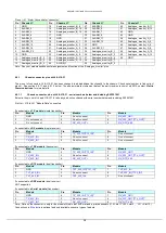
Chassis connector pin out J4 & J19-31 - serial numbers above and including SN1221902
Below is the pin out of J4 and J19-J31 for all later production chassis with serial number above and including SN1221902.
The backplane is marked ‘
Issue C
’ – this description can be found on the PCB between slot 13 and 14 when viewed from the front.
Pin Out
– J19 to J31 “Module Data” connectors
If connected to a
TX module
(single transmitter)
Pin
Module
Pin
Module
Pin
Module
1
GND
4
Do not connect
7
RX_422_OUT-
2
Do not connect
5
Do not connect
8
RX_232_OUT [TTL_OUT]*
3
Do not connect
6
RX_
9
RX_RTS_485
If connected to a
RX module
(single receiver)
Pin
Module
Pin
Module
Pin
Module
1
GND
4
TX_232_IN [TTL_IN]*
7
Do not connect
2
TX
5
Do not connect
8
Do not connect
3
TX_422_IN-*
6
Do not connect
9
Do not connect
If connected to a
TRX module
(transceiver)
Pin
Module
Pin
Module
Pin
Module
1
GND
4
TX_232_IN [TTL_IN]*
7
RX_422_OUT-
2
TX
5
Do not connect
8
RX_232_OUT [TTL_OUT]*
3
TX_422_IN-*
6
RX_
9
RX_RTS_485
If connected to a
DTX module
(dual transmitter)
Pin
Module
Pin
Module
Pin
Module
1
GND
4
TX1_232_IN [TTL1_IN]*
7
TX2_422_IN-
2
TX1
5
Do not connect
8
TX2_232_IN [TTL2_IN]*
3
TX1_422_IN-
6
TX2
9
Do not connect
If connected to a
DRX module
(dual receiver)
Pin
Module
Pin
Module
Pin
Module
1
GND
4
RX1_232_OUT [TTL1_OUT]*
7
RX2_422_OUT-
2
RX1_
5
RX1_RTS_485
8
RX2_232_OUT [TTL2_OUT]*
3
RX1_422_OUT-
6
RX2_
9
RX2_RTS_485
If connected to a
Serial module
(transceiver)
Pin
Module
Pin
Module
Pin
Module
1
GND
4
TX_232_IN [TTL_IN]*
7
RX_422_OUT-
2
TX
5
Do not connect
8
RX_232_OUT [TTL_OUT]*
3
TX_422_IN-*
6
RX_
9
RX_RTS_485
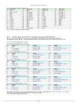
Note: Data on the connector is only for the module fitted in that 5HP slot and is printed beneath (J19 = slot 1, J20 = slot
2 … J31 = Slot 13)
Connections in
Blue
are optional and only available on some types of module
Pin out
– J4 “Power Concentrator” connector*


