HRK3-HB-7
V
IA
L
ITE
HD
3U
CHASSIS
H
ANDBOOK
25
6.7
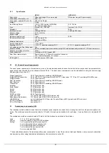
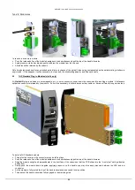
7HP blanking panel installation (slot 14)
Blanking panels should be the last panel installed into your chassis
To install the blanking panel
Firstly inspect the blanking panel ensure that the plastic barbs are in good condition
Align the plastic barbs with the larger holes centrally above and below the slot on the chassis top and bottom rails.
Firmly push the panel in until you feel the barbs click
To remove the blanking panel
Pull the blanking panel towards you, it may be necessary to use extra leverage.
Discard the panel as the plastic barbs will now be over stressed and will not provide a reliable fixing.
6.8
6HP blanking panel installation (slots 15, 16)
Blanking panels should be the last panel installed into your chassis
To install the blanking panel
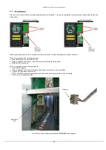
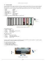
Push the release button of the panel handle down and simultaneously pull the top of the handle forwards.
Align the panel upright and perpendicular to the front face of the chassis
so that the plate slides into the “straight” card guides.
Gently push the panel down its guide, applying pressure via the handle.
As the panel is fully mated the top of the handle should snap back and lock in position.
The pawls of the handle should be fully engaged in the matching slots.
To remove the blanking panel
Push the release button of the panel handle down and simultaneously pull the top of the handle forwards.
Apply pressure via the handle and gently withdraw the panel from the chassis.
6.9
Separate blindmate panels
If you wish to pre-populate and cable your blindmate chassis in advance, chassis plates can be purchased as spares, details below.
PPM part number 85058
ViaLiteHD, Chassis plate, Blind
mate (Type ‘D’), 1 * SMA 50ohms, 1 * SC/APC
PPM part number 85059
ViaLiteHD, Chassis plate, Blind
mate (Type ‘D’), 2 * SMA 50ohms, 2 * SC/APC
PPM part number 85060
ViaLiteHD, Chassis plate, Blind
mate (Type ‘D’), 1 * BNC 75ohms, 1 * SC/APC
PPM part number 85061
ViaLiteHD, Chassis plate, Blind
mate (Type ‘D’), 2 * BNC 75ohms, 2 * SC/APC
PPM part number 85064
ViaLiteHD, Chassis plate, Blind
mate (Type ‘D’), 1 * F-Type 75ohms, 1 * SC/APC
PPM part number 85065
ViaLiteHD, Chassis plate, Blind
mate (Type ‘D’), 2 * F-Type 75ohms, 2 * SC/APC
PPM part number 85066
ViaLiteHD, Chassis plate, Blind
mate (Type ‘D’), 2 * SMA 50ohms
PPM part number 85067
ViaLiteHD, Chassis plate, Blind
mate (Type ‘D’), 3 * SMA 50ohms
PPM part number 85068
ViaLiteHD, Chassis plate, Blind
mate (Type ‘D’), 4 * SMA 50ohms
PPM part number 85069
ViaLiteHD, Chassis plate, Blind mate
(Type ‘D’), Duplexed, 1 * SMA 50ohms, 1 * SC/APC
PPM part number 85070
ViaLiteHD, Chassis plate, Blind mate
(Type ‘D’), Duplexed, 1 * BNC 75ohms, 1 * SC/APC
PPM part number 85071
ViaLiteHD, Chassis plate, Blind mate
(Type ‘D’), 1 * BNC 50ohms, 1 * SC/APC
PPM part number 85072
ViaLiteHD, Chassis plate, Blind mate
(Type ‘D’), 2 * BNC 50ohms, 2 * SC/APC.
PPM part number 85073
ViaLiteHD, Chassis plate, Blind mate
(Type ‘D’), 2 * SC/APC
PPM part number 85103
ViaLiteHD, Chassis plate, Blind mate
(Type ‘E’), 1 * SMA 50ohms, 1 * LC/APC
PPM part number 85104
ViaLiteHD, Chassis plate, Blind mate
(Type ‘E’), 2 * SMA 50ohms, 2 * LC/APC
PPM part number 85105
ViaLiteHD, Chassis plate, Blind mate
(Type ‘E’), 1 * BNC 75ohms, 1 * LC/APC
PPM part number 85106
ViaLiteHD, Chassis plate, Blind mate
(Type ‘E’), 2 * BNC 75ohms, 2 * LC/APC
PPM part number 85107 ViaLiteHD, Chassis plate, Blind mate
(Type ‘E’), 2 * SMA 50ohms
PPM part number 85108 ViaLiteHD, Chassis plate, Blind mate
(Type ‘E’), 3 * SMA 50ohms
6.10
Electrical power connection
Power should be applied to the chassis with the supplied power cords (AC chassis only), if these are not used a suitable alternative should
be used. A substitute power cord should be rated as following
Current rating
10A
Voltage rating
To match your installation requirement
Mating connector (AC)
IEC 60320 C13 socket (HRK3S)
Mating connector (DC)
Plug, stripped cable or fork terminal suitable for mounting to 4mm screw terminal (HRK3S-DC))
You should ensure that all cable is routed carefully to protect them from mechanical damage especially those caused by sharp edges.
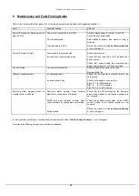
Each chassis has two separate power feeds these separately feed, slots 15 and 16, as shown below. To fully isolate the chassis BOTH
power feeds MUST be removed.

