


Page 22 of 32
4.4.1
R emove the packaging/protection from the Radiant Tubes and ensure that they are clear internally. It is
recommended that the appliance is suspended in sections which are joined by the use of Torctite
Couplings once in position.
4.4.2
Place one Radiant Tu be (long), one Radiant Tube (short) and one Radiant Tube Assy (containing
turbulator) on trestles providing 150mm minimum clearance above the floor, and assemble the five Hanger
Brackets to the Radiant Tubes and Radiant Tube Assy using one'U' bolt per bracket (from fastenings
pack). Position the Hanger Brackets along the Radiant Tubes and Radiant Tube Assy as shown in Fig. 16.
Ensure that the welded seams of the tubes are in contact with the Hanger Brackets. i.e. facing away from
the reflector. Tighten the nuts sufficiently to retain the Hanger Brackets. Do not overtighten.
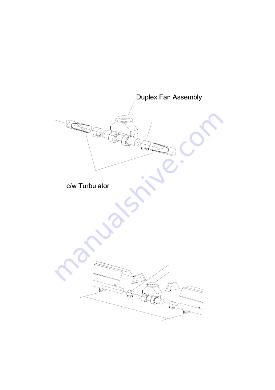
IMPORTANT: ensure that the turbulator is positioned adjacent to the Duplex Fan assembly and orientated
as shown in Fig. 17. Failure to assemble the Radiant Tubes with their welded seams facing away from the
reflector will void the manufacturers warranty.
Fig. 17
4.4.3
Place one Torctite Coupling over the relevant end of the long Radiant Tube (see Fig. 16) ensuring that it
engages fully, up to the stop. Assemble the Control Box to the Radiant Tube ensuring that it engages fully
into the Torctite Coupling (up to the stop) and is positioned vertically with the door latch uppermost (Fig. 5).
Tighten the screws of the Torctite Coupling to secure the Control Box to the Radiant Tube, taking care to
support the control box in line with axis of the tube.
NOTE
: Tighten the Torctite Coupling screws alternately whilst continually checking for slackness of the
joint.
4.4.4
The three sections should now be raised and suspended from previously fixed chains or drop rods as
detailed in Section 3.1, at suspension points indicated in Fig. 16 & 18. Rope or webbing slings should be
used when lifting from above. If using a forklift to position the appliance sections, ensure that they are
balanced on the forks prior to lifting.
Fig. 18
Torctite Coupling
Radiant Tube (4" x 4.572m)
'B'
S
840
S
S
'B'
S
Torctite Coupling
Duplex Fan
Assembly


