cover plug from the outlet flue length and insert a CO
2
measuring instrument.
2. Turn "ON" the main electricity supply and check that the
following sequence of events occur.
i) Burner fan runs.
ii) Ignition spark is heard
iii) Main gas valves open
iv) Main gas flame is established.
3. Check that the main burner gas pressure agrees with that
in Tables 3.1 or 3.2. If necessary adjust the main burner
gas pressure
(Fig 2a - 3 or Fig 2b - 2).
4. Measure the CO
2
content of the flue gases. If necessary
adjust the combustion air damper of the burner
(Refer to
the
Burner Supplement)
to obtain a reading of 9.0 - 9.5%.
5. Turn "OFF" the main electricity supply, remove pressure
gauge and refit sealing screw in pressure test point and
flue sample point cover plug.
6.5
Final Soundness Test
1. After making final gas rate checks all joints on the gas
controls assenbly must be tested for soundness using leak
detection fluid.
6.6
Flame Safeguard
1. Whilst the burner is in operation close the gas service
valve. The burner should go to lockout within 1 second.
6.7
Handing over the Air Heater
Hand the Users Instructions to the user or purchaser for
retention and instruct in the efficient and safe operation of
the air heater and associated controls.
Adjust the automatic controls to those values required by
the User.
Finally, advise the user or purchaser that, for continued
efficient and safe operation of the air heater, it is important
that servicing is carried out annually.
In the event that the premises are not yet occupied turn off
the gas and electricity supplies and leave instructional
literature adjacent to gas meter.
7.
Servicing
WARNING:
Always switch off and disconnect electricity
supply and close the gas service valve before carrying out
any servicing work or replacement of failed components.
7.1
General
Full maintenance should be undertaken not less than once
per year. After any servicing work has been complete or any
component replaced the air heater(s) must be fully
commissioned and tested for soundness as described in
Section 6.
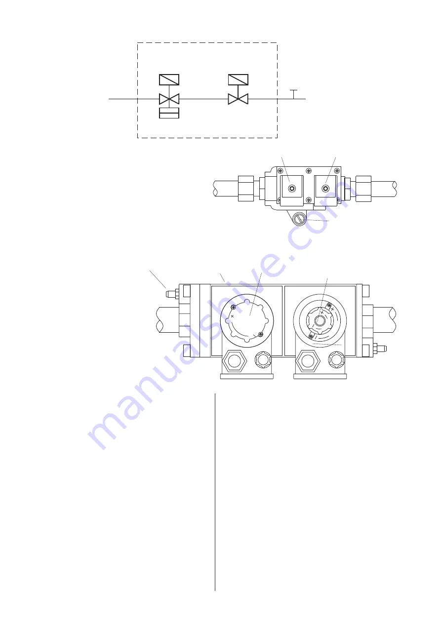
Fig 1 Gas Controls Schematics
1st Main Gas
Safety Shut-off
Valve
2nd Main Gas
Safety Shut-off
Valve
Main Gas
Governor
Gas
Inlet
To Burner
Pressure
Test
Point
Fig 2a Gas Controls Layout NCA-G 100, 150
1) 1st Main gas safety shut off valve.
2) 2nd Main gas safety shut off valve.
3) Main burner pressure adjustment screw.
Notes:-
i) Electrical connection plugs not shown.
Fig 2b Gas Controls Layout NCA-G 200, 300
1) M a i n g a s s a f e t y s h u t - o f f
valves.
2) M a i n b u r n e r p r e s s u r e
adjustment screw.
3) Inlet Pressure test point.
4) F l o w r a t e a n d v a l v e o p e n i n g
speed adjustments.
V
S
T
A
R
T
V
M
A
X
RE
G.
SE
TPO
IN
T
Gas
Inlet
To
Burner
1
2
3
4
3
6
1
2
3
Gas
Inlet
To
Burner


