


CPx Gas or Oil Cabinet Heater Range Issue 2.1 June 2014 Page 21
Electrical Connections
Wiring external to the air heater must be installed in accor-
dance with the I.E.E. Regulations for Electrical Installations
and any local regulations which apply. Wiring should be
completed in flexible conduit.
Heaters are for use with 230V, 1N, 50Hz or 400V, 3N, 50Hz
supplies (see heater data plate).
The method of connection to the main electricity supply
must:-
- facilitate the complete electrical isolation of the heater(s)
that will prevent remote activation of the heater during
servicing.
- be in a readily accessible position adjacent to the heater(s).
- serve only the heater(s).
- have a contact separation of at least 3mm in all poles. See
the wiring diagram for the heater electrical connections.
All units are fully prewired and only require final connections
for the incoming mains supply. Heaters not supplied with
inbuilt time and temperature controls will also require
completion of the external control circuit (230V) via a room
thermostat, time clock etc. and, if applicable, the remote low
level lockout reset.
All heaters must be earthed.
Reference must be made to Table 3 Page 21 to ascertain the
electrical loading of the unit(s) being installed so that cables
of adequate cross-sectional area are used for the electrical
installation. The length of the conductors between the cord
anchorage and the terminals must be such that the current
carrying conductors become taut before the earth conductor
if the cable or cord slips out of the cord anchorage. All exter-
nal controls must be of an approved type.
Heaters supplied less main fan must be electrically
interlocked to the air movement system so that this is started
in the same manner as the air heater fan would be viz. A
connection from the appropriate heater terminal (see wiring
diagram with the heater) must be made to one side of the fan
motor contactor coil, the other side of the coil being connect-
ed to Neutral. Under no circumstances must the fan motor
electrical supply be taken direct from the internal wiring of
the heater.
A =
2 core and earth (Single Phase)
4 core and earth (Three Phase)
B = Powrtrol = 4 core and earth
Powrtrol RR = 4 core and earth
MC200 =
4 core and earth
C =
2 core screened (MC200 model only)*
*(screen must be grounded only
at the MC200)
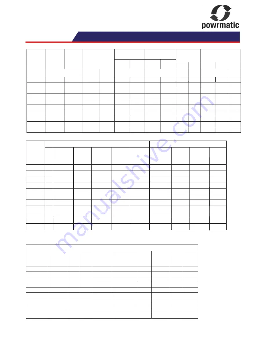
3.1 Technical Data
Table 2. Specifications
Fan motor
Gas
Oil
Model
Nom.
Input
(Nett)
Air
Volume
Standard
Motor
Uprated
Motor
Output
Maximum duct
resistant
Standard
Motor
Uprated
Motor
Kw
m³/s
pa
Kw
Weight
Fuel
Connection
Size
Kg
CPx
CPx
/NCA
CPx
/EA
CPx120
R
c
¾
341
130.4
120.0
2.3040
140
N/A
2.2
N/A
¼”
BSP
448
458
CPx300
315.2
R
c
1¼
556
290.0
5.7600
150
250
5.5
7.5
3
/
8
”
BSP
TBA TBA
CPx60
65.2
60.0
1.1520
185
N/A
0.550
N/A
R
c
¾
173
¼”
BSP
210
215
231
210
215
CPx90
90.0
97.8
1.7280
100
N/A
1.1
N/A
R
c
¾
241
¼”
BSP
304
304
CPx150
163.0
150.0
2.8800
175
240
2.2
3.3
R
c
1¼
386
¼”
BSP
535
546
CPx175
190.2
175.0
3.3600
190
250
3.3
5.5
R
c
1¼
530
¼”
BSP
TBA TBA
CPx200
217.4
200.0
3.8400
100
200
4.0
5.5
R
c
1¼
530
¼”
BSP
TBA TBA
CPx250
271.7
250.0
4.8000
N/A
150
4.0
5.5
R
c
1¼
556
3
/
8
”
BSP
TBA TBA
CPx30
194
188
32.61
30.0
R
c
½
0.5760
N/A
0.373
N/A
168
¼”
BSP
R
c
½ ¼”
BSP
206
CPx45
48.9
45.0
0.8640
m³/h
8294
20736
4147
6221
10368
12096
13824
17280
2074
3110
322
N/A
0.550
N/A
Table 3. Electrical Data
Table 4.1
Burner Pressures - Natural Gas - Group H - G20 - Net CV (H
i
) = 34.02MJ/m³
Riello Burners
Air Gas Start Gas Main Burner
Nom. Nett
Model
Type Head Gate Pressure Pressure
Input Gas Rate CO
2
Flue T.
No
No
mbar
mbar
kW
m³/h
% °C
CPxG 30
GS 5
0
N/A
N/A
4.5
32.3
3.42
9.1
145
CPxG 45
GS 10
FF
N/A
N/A
4.0
49.0
5.18
8.8
160
CPxG 60
GS 10
1
N/A
N/A
3.8
64.6
6.84
8.9
143
CPxG 90
GS 10
FF
N/A
N/A
5.3
98.3
10.40
9.0
170
CPxG 120
GS 20
2
N/A
2.7
4.5
127.4 13.48
8.9
156
CPxG 150
GS 20
FF
N/A
3.2
5.7
162.9 17.24
9.2
163
CPxG 175
GS 20
FF
N/A
2.9
5.8
190.1
20.11
8.8 157
CPxG 200
GAS 3
4
4
2.9
7.1
215.9
22.84
9.0 148
CPxG 250
GAS 3
FF
7
3.7
8.5
269.9
28.56
9.3 153
CPxG 300
GAS 3
FF
7
4.5
10.2
316.2
31.79
9.5 175
Notes:
CO
2
values and Nett flue gas temperatures are given for guidance and measured values will depend on site conditions.
FF = Fully Forward
Minimum
Inlet pressure
17.5mbar
WARNING:
Always switch off and disconnect
electricity supply, close the gas service valve or
turn off the oil supply before carrying out any
servicing work or replacement of failed compo-
nents.
4.1.1 General
Full maintenance should be undertaken not less than
once per year. After any servicing work has been com-
plete or any component replaced the air heater(s) must
be fully commissioned and tested for fuel tightness as
described in Section 2.5. Page 17
4.1.2 Burner Servicing/Maintenance
1. Refer to the burner instructions supplied with the
heater and complete the servicing/maintenance instruc-
tions therein. Note: In the case of gas burners ignore any
references in the burner supplement to the gas controls
assembly.
4.1.3 Heat Exchanger Cleaning
1. Removing the upper rear panel of the heater exposes
the heat exchanger rear clean out panel.
2. Removing the fan/limit thermostat(s) as described in
4.1.6.6.4, Page 25 disconnecting the flue and then
removing the upper front panel of the heater exposes the
heat exchanger front clean out panels. If the flue cannot
be disconnected removal of the side panels exposes the
upper front header side clean out plates.
3. Remove the nuts securing the clean out panel(s) as
appropriate and remove panel(s).
4. If heat exchanger baffles are fitted, withdraw them.
5. Brush through heat exchanger tubes and remove loose
material using a vacuum cleaner.
6. If it is necessary to also gain access to the combustion
chamber disconnect the fuel and electrical connections
from the burner. Remove the nuts securing the burner to
the heater and withdraw the burner from the burner tube.
7. Reassemble all components in reverse order. Note:
Replace any gaskets with new ones.
4.1.4 Fan Assembly
1. Remove the lower panels of the heater to gain access
to the fan section.
2. Inspect the fan blades to see that they are not dam-
aged and that there is no excessive build up of deposits
that could give rise to an imbalance. If necessary clean
the fan blades using a stiff brush and vacuum cleaner.
3. Replace panels accordingly.
4.1.5 Oil Filter (if applicable)
1. Release the securing bolt, or unscrew the filter bowl, to
access the filter.
2. Clean the filter or replace as deemed necessary.
3. Refit bowl ensuring that seals are correctly in place.
4.1.6 Replacement of Faulty
Components
4.1.6.1 Burner Components
1. Refer to the burner instructions supplied with the heater
for information regarding replacement of components
within the burner.
4.1.6.2 Gas Controls Assembly (if
applicable)
1. Remove the electrical connections from the gas control
block.
2. Release the nuts securing the inlet and outlet flanges to
the gas control block and lift out the gas control block. Fit
the replacement assembly in reverse order ensuring the
valve is correctly orientated =for the direction of gas flow.
4.1.6.3 Main Air Fan and Motor
Important: On 3ph heaters fitted with 3ph main
fan motors ensure that the fan direction of
rotation corresponds with the direction of rotation
arrow on the fan guard or case. If necessary
reverse the direction of rotation by interchanging
any two of the motor live leads at the terminal
strip in the electrical panel. Should it be neces-
sary to remove one or more of the fans for clean-
ing proceed as follows.
4.1.6.3.1 CPx 30 - CPx 120
Note: These heaters are fitted with direct drive
fan units.
1. Disconnect the fan motor electrical leads from
the terminal strip (Refer to wiring diagram
supplied with the heater)
2. Remove the two screws, one on each side of
the fan mounting flange, that secure the fan to the
fan shroud.
3. Remove the screws securing the heat
exchanger mounting frame to the fan shroud on
the side that the fan is going to be withdrawn.
4. Withdraw the fan from the slide rails.
5. Reassemble in reverse order.
4.1.6.3.2 CPx 150 - CPx 300
Note: These units are fitted with belt driven main
air fans.
1.Remove the lower side panel(s).
2. Release the motor mounting plate securing
screws and then remove the belt tension by
turning the tension adjustment screw anticlock
wise. Remove the fan belts.
3. Remove the screws securing the fan mounting
feet to the heater framework and remove the fan.
It may be necessary to re-orientate the fan within
the fan compartment and also to release the fan
shroud fixings in order to pass the fan through
the heater frame. On units with twin or triple fan
sets on a common fan shaft it will be necessary to
first remove the fan shaft.
4. Inspect the fan belts and if necessary replace
with new.
5. Replace components in reverse order.
6. Do not over tension the fan belts. There should
be approximately 15mm of deflection when
downward pressure is applied to the belt(s)
halfway between the motor and fan pulleys.
Fig 3 Fan belt tension setting
4.1.6.6.4 Fan / Limit Thermostat Hon-
eywell L4064B
NOTE:
Larger heaters have two fan and limit
thermostats fitted.
Either one will start the main fans and either one
will shut down the burner in the event of an over-
heat situation.
1. Squeeze the sides of the cover and remove
cover by pulling forward.
2. Release wiring from clamp terminals by push-
ing a small screwdriver into the clamp release
holes adjacent to the clamps.
3. Remove the 2 screws securing the thermostat
to the heater panel and withdraw thermostat.
4. Reassemble new unit in reverse order referring
to the heater wiring diagram to ensure correct
wiring location.
Important:
A replacement fan/limit thermostat
may have a brass link between the bottom fan
terminal and the bottom limit terminal (situated in
the slot between the two terminals). This
MUST
be removed, by breaking the link off using a pair
of thin nose pliers, before the replacement
thermostat is installed.
Standard Motor
Uprated Motor
Fitted to EA models as standard
Nominal Plate Start
Run
Fuse Nominal Start Run Fuse
Model ph Motor Amps Amps Amps Rating Motor Amps
Amps Amps
R.P.M.
(A) (A) (A) (A) R.P.M. (A)
(A) (A)
CPx30
1
1370 3.3 6.5 4.2 5 N/A N/A
N/A
N/A
CPx45
1
1250 5.0 9.1 5.0 7 N/A N/A
N/A
N/A
CPx60
1
930 3.1 8.1 4.7 7 N/A N/A
N/A
N/A
CPx90G
1
900 9.8 18.0 7.2 10 N/A N/A
N/A N/A
CPx90O
1
900 9.8 18.0 6.5 10 N/A N/A
N/A N/A
CPx120
3
900 5.3 13.1 4.8 7 N/A N/A
N/A N/A
CPx150 3 1500 4.91
32.5
5.1
7
1500
25.0 5.75
10
CPx175 3 1500 6.47
20.8
6.9
10
1500
35.0 11.0
15
CPx200 3 1500 8.14
38.0
6.5
10
1500
35.0 8.83
15
CPx250 3 1500 8.14
58.0
9.0
15
1500
35.0 11.65
15
CPx300 3 1500 10.9
80.0
9.7
15
1500
32.0 14.4
15


