


CPx Gas or Oil Cabinet Heater Range Issue 2.1 June 2014 Page 13
2.1.1 General
Before installation, check that the local distribution condi-
tions, fuel specification, and adjustment of the appliance
(see data plate) are compatible.
Important:
Copper Sulphide / ‘Black Dust’
In some areas of the UK, particularly Northern Ireland,
problems have been experienced with copper sulphide
(more commonly referred to as ‘Black Dust’) forming on
the inner surfaces of copper gas supply pipework. This
dust can enter the gas stream and may lead to blockages
of valves, filters and injectors.
If this heater is being installed in an area where ‘Black
Dust’ is known to be a problem, and copper gas supply
pipework is used, it is recommended that a filter having a
stainless steel 50 micron mesh and suitable for Natural
Gas is fitted at the inlet to the appliance immediately
downstream of the main appliance isolation valve. The
end user should be advised that the filter will require
periodic cleaning or replacement at least once per year,
during the annual service, or more often if the problem is
severe.
2.1.2 Location
The location chosen for the air heater must permit:
- the provision of a satisfactory flue system and an
adequate air supply.
- adequate space for servicing and air circulation around
the air heater.
The heater(s) must not be installed in conditions for which
it is not specifically designed e.g. where the atmosphere
is corrosive or salty, and they are not suitable for outdoor
use unless the CPx/EA style is specified. CPx/EA heaters
must be installed on a plinth such that there is a minimum
distance of 0.5m between ground level and the lowest
point of any air inlet grilles.
Where the location of the air heater is such that it might
suffer external mechanical damage e.g. from overhead
cranes, fork lift trucks, it must be suitably protected.
CPx heaters are for normal operation within an ambient
temperature range of -10 to 25°C.
The air heater must be installed in accordance with the
rules in force and the relevant requirements of any fire
regulations or insurance company's requirements apper-
taining to the area in which the heater is located, particu-
larly where special risks are involved such as areas where
petrol vehicles are housed, where cellulose spraying is
carried out, in wood working departments etc.
IMPORTANT:
Heaters shall not be installed in:-
a) Those parts of spaces within buildings that
have been classified as hazardous areas as
defined in BS EN 60079-14.
b) Where there is a foreseeable risk of flammable
particles or gases or corrosion inducing gases or
vapours being drawn into either the heated air
stream or the air for combustion. In such cases
installation may only proceed if both air sources
are from an uncontaminated source, preferably
from outside the building. It may also be neces-
sary to purge the air heater before the burner is
allowed to fire. In certain situations where only
airborne particles are present it may suffice to fit
filters on the main air inlet duct of the heater.
Advice in these instances must be obtained from
Powrmatic Ltd.
c) In areas subjected to significant negative pres-
sures due to extract systems.
2.1.3 Installing the Air Heater
If necessary consideration should be given to mounting
the heater on resilient pads, or equivalent, to minimize
transfer of noise and vibration to the structure of the build-
ing.
Floor mounted heaters must be installed on a level
noncombustible surface.
Heaters mounted at high level must be supported on a
purpose designed platform or framework that is suspend-
ed from vertical drop rods, chains or straps or mounted on
specifically designed cantilever brackets from a non-com-
bustible wall. The method of installation support must be
capable of adequately supporting the weight of the unit
(See Table 2, Page 21) and any ancillary equipment.
Before installing the heater the existing structure must be
inspected to ensure it is suitable. All supports should be
protected against the effects of rust or corrosion.
Whichever method of mounting the air heater is used the
following minimum clearances for installation and servic-
ing must be observed.
Important:
CPx 250 & CPx 300 heaters have louvred lower
panels on both sides. The minimum clearance of
0.15m is increased to 0.5m.
Important:
Smaller heaters are supplied with one blank side
panel and one louvred side panel. If the heater is
installed against a wall ensure that the blank
panel is facing the wall, interchanging the two side
panels if necessary.
Any combustible material adjacent to the air
heater and the flue system must be so placed or
shielded as to ensure that its temperature does
not exceed 65 °C.
If the method of mounting allows for any move-
ment of the heater it is essential that all gas, duct,
and electrical connections to the heater are made
with flexible connections to maintain continuity of
connection.
2.1.4 Combustion & Ventilation Air
Supply
There shall be provision for a supply of air for combustion
and, in the case of heaters installed in an enclosure or
plant room, for ventilation.
Actual values relating to the details below
1) Installation in the heated space
In buildings with a design air change rate of 0.5 /h or great-
er, additional natural or mechanical ventilation is not
necessary. In buildings not having a design air change
rate of 0.5 /h the following apply.
Natural Ventilation
Grilles having a free area of at least 2cm² per kW of rated
heat input shall be provided at low level i.e. below the level
of the heater flue connection.
Mechanical Ventilation
Must ensure that the space air change rate is at least
0.5/h, must be of the ‘input’ type and interlocked to ensure
the heaters cannot work if the input system is not working.
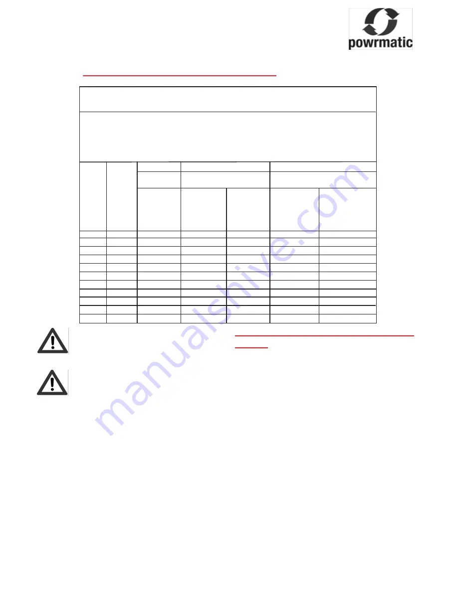
CPx Combustion & Ventilation Air Supply
Type B23 Installation
These refer to section 2.1.4. of the instructions
Air vents shall be permanently open.
Figures in column 1 are for heaters installed in the space they are heating.
Figures in column 2 are for heaters installed in a plant room, ventilation to outside air.
Figures in column 3 are for heaters installed in a enclosures, ventilation to outside air.
In all cases figures are per heater installed.
For multi heaters installations the appropriate values for each heater must be added together.
1
2
3
In the
In a plant room
In an enclosure
Space
CPx
Input
Low
Low
High
Low
High
kW
Level
Level
Level
Level
Level
Grille
Grille
Grille
Grille
Grille
Free
Free
Free
Free
Free
Area
Area
Area
Area
Area
cm
2
cm
2
cm
2
cm
2
cm
2
30
32.29
64.6
129.2
64.6
322.9
161.5
45
48.97
97.9
195.9
97.9
489.7
244.8
60
64.62
129.2
258.5
129.6
646.2
323.1
90
98.31
196.6
393.2
196.6
983.1
491.5
120
127.43
254.9
509.7
254.9
1274.3
637.1
150
162.90
325.8
651.6
325.8
1629.0
814.5
175
190.07
380.1
760.3
380.1
1900.7
950.4
200
215.87
431.7
863.5
431.7
2158.7
1079.3
250
269.86
539.7
1079.4
539.7
2698.6
1349.3
300
316.25
632.5
1265.0
632.5
3162.5
1581.2
2) Installation in plant rooms or enclosures
There must be permanent air vents communicating direct-
ly with the outside air, at high level and at low level.
Plant Rooms
Low level (inlet) 4cm²/kw of total rated net heat input
High level (outlet) 2cm²/kw of total rated net heat input
Enclosures
Low level (inlet) 10cm²/kw of total rated net heat input
High level (outlet) 5cm²/kw of total rated net heat input
Mechanical Ventilation
The minimum flow rate of ventilation shall be 4.14m³/h per
kilowatt of total rated heat input.
2.1.5. Gas Connection (if applicable)
• A servicing valve and union must be fitted at the gas inlet
to the heater to facilitate servicing.
• The gas supply to the air heater must be completed in
solid pipe work and be adequately supported.
• Heaters suspended by drop rods, straps or chains must
have a flexible connection as the final link between the
gas supply pipe work and the heater. Sufficient slack must
be left in the connection to take account of normal move-
ment of the heater.
Warning:
When completing the final gas connection to the
heater do not place undue strain on the gas pipe
work of the heater.
2.1.6. Oil Connection (if applicable)
Refer to the supplied burner installation instructions for
details regarding oil supply options.
2.1.7. Air Distribution System
For free-blowing units used in buildings having a low heat
loss i.e. where single units are required to cover a large
floor area, and in buildings with high roof or ceiling heights
Calecon thermal economiser units should be fitted to
ensure even heat distribution and minimise stratification.
Care should be taken to avoid impeding the heater air
throw with racking, partitions, plant or machinery etc.
Various outlet configurations are available as optional
extras to modify the air throw pattern to suit particular site
conditions.
CPx*/D models are designed for use with duct work to
more precisely define the point of air delivery, and /or
provide ducted return air or ducted fresh air inlet. All duct-
ing must be independently supported of the air heater.
All delivery and return air ducts, including air filters,
jointing and any insulation or lining must be constructed
entirely of materials which will not contribute to a fire, are
of adequate strength and dimensionally stable for the
maximum internal and external temperatures to which
they are to be exposed during commissioning and normal
operation.
Where inter-joist spaces are used as duct routes they
should be suitably lined with a fire-resisting material.
A full and unobstructed return air path to the air heater(s)
must be provided. If the air heater(s) is installed in a plant
room the return air intake(s) and the warm air outlet(s)
from the heater(s) must be fully ducted, into and out of the
plant room to avoid interference with the operation of the
heater from other equipment.
The openings in the structure of the plant room through
which the ducting passes must be fire stopped. Care must
be taken to ensure that return-air intakes are kept clear of
sources of smells and fumes, and where there is any
possibility of pollution of the air by dust, shavings etc.,
precautions must be taken to prevent contamination.
If necessary suitable barrier rails should be provided to
prevent any combustible material being placed within
900mm of the outlets.
Joints and seams of supply ducts and fittings must be
securely fastened and made airtight.
It is recommended that ducting should be connected to
the heater spigots via an airtight flexible coupling of
noncombustible material. Before fitting coupling it must
be ensured that an adequate clearance will be maintained
between the ends of the ducting and the heater spigots.
If required sound attenuators may be fitted in inlet and
outlet ducts to reduce airborne fan noise. Materials used
in outlet sound attenuators must be capable of withstand-
ing 100°C air temperature without any deterioration.
2.1.8 Room Thermostat Siting
If a remote room thermostat, or controller with an integral
sensor, is used it should be fitted at a point which will be
generally representative of the heated area as far as
temperature is concerned. Draughty areas, areas
subjected to direct heat e.g. from the sun, and areas
where the air movement is relatively stagnant e.g. in
recesses, are all positions to be avoided for siting the
thermostat.
The thermostat should be mounted about 1.5m (5ft) from
floor level.
Any room thermostat, frost thermostat, time clock etc.
must be suitable for switching 230V, 5A and must be of
the 'snap action' type to minimise contact bounce.
For electrical connections of external controls see the
accompanying wiring diagram.
Electrical Connections
Wiring external to the air heater must be installed in accor-
dance with the I.E.E. Regulations for Electrical Installations
and any local regulations which apply. Wiring should be
completed in flexible conduit.
Heaters are for use with 230V, 1N, 50Hz or 400V, 3N, 50Hz
supplies (see heater data plate).
The method of connection to the main electricity supply
must:-
- facilitate the complete electrical isolation of the heater(s)
that will prevent remote activation of the heater during
servicing.
- be in a readily accessible position adjacent to the heater(s).
- serve only the heater(s).
- have a contact separation of at least 3mm in all poles. See
the wiring diagram for the heater electrical connections.
All units are fully prewired and only require final connections
for the incoming mains supply. Heaters not supplied with
inbuilt time and temperature controls will also require
completion of the external control circuit (230V) via a room
thermostat, time clock etc. and, if applicable, the remote low
level lockout reset.
All heaters must be earthed.
Reference must be made to Table 3 Page 21 to ascertain the
electrical loading of the unit(s) being installed so that cables
of adequate cross-sectional area are used for the electrical
installation. The length of the conductors between the cord
anchorage and the terminals must be such that the current
carrying conductors become taut before the earth conductor
if the cable or cord slips out of the cord anchorage. All exter-
nal controls must be of an approved type.
Heaters supplied less main fan must be electrically
interlocked to the air movement system so that this is started
in the same manner as the air heater fan would be viz. A
connection from the appropriate heater terminal (see wiring
diagram with the heater) must be made to one side of the fan
motor contactor coil, the other side of the coil being connect-
ed to Neutral. Under no circumstances must the fan motor
electrical supply be taken direct from the internal wiring of
the heater.
A =
2 core and earth (Single Phase)
4 core and earth (Three Phase)
B = Powrtrol = 4 core and earth
Powrtrol RR = 4 core and earth
MC200 =
4 core and earth
C =
2 core screened (MC200 model only)*
*(screen must be grounded only
at the MC200)


