background image


30 

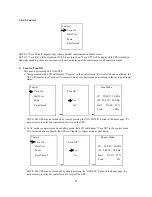
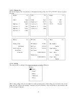
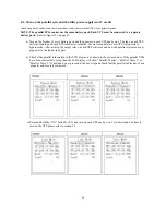
3)  Battery setting 

(available in all operational modes)


 Interface 

 Description 


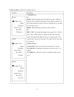
1. Dischg Protect : 


  Battery : 


1.1  


Enable : 

Battery discharge protection function is enabled.


When  the  


        DisChg Protect : 

  UPS has been continuously operating in “battery/battery test mode”, the 

                            Enable 

  UPS will automatically shut down when the discharge time set by option  

                    990 Minute  

  1.2 below has expired. 

        Batt Test Type : 


Disable : 

Battery discharge protection function is disabled.


              Short Time : 


1.2 

              Till Batt Low 


0000 ~ 1500 : 

The maximum discharge time ranging from 0 to 1500 mi- 


  nutes.  When  “Dischg Protect” is enabled the UPS will shut down to 


protect the battery after backup time arrives. If “Dischg protect” is dis- 

  Battery : 

  abled then this setting is not functional. The default value for this setting  


  is 990 minutes. 

        DisChg Protect : 


2. Batt Test Type : 

                            Enable 


2.1 Short Time : 

Battery test will last for a duration of 10 seconds. 

                    990 Minute  


2.2 Long Time : 

The duration of the battery test can be set to 01 ~ 99  

        Batt Test Type : 

  minutes. 

              Short Time : 


2.3 Till Batt Low : 

Battery test will not stop until the battery voltage  

                    10 Minute 

  is low.    


  Battery : 


        DisChg Protect : 


                            Enable 


                    990 Minute  


        Batt Test Type : 


              Short Time : 


                    10 Second 


Summary of Contents for ACDEF6000-22

Page 1: ...ant instructions for models ACDEF6000 22 E240 22 A 6KVA UPS BATTERY CABINET Follow these instructions during the unpacking installation and maintenance of the UPS If you have a problem with the UPS please refer to this manual before calling technical services POWERVAR 1450 South Lakeside Drive Waukegan IL 60085 8301 T 847 596 7000 800 369 7179 F 847 596 7100 ...

Page 2: ...A01 00027 Rev A ...

Page 3: ...ion 2 2 Rack Installation 2 2 1 Attaching the mounting ears 2 2 2 Mechanical Fixing of 19 inch Units 2 2 3 Assembly Steps 2 3 Electrical Preparations for UPS Installation 2 3 1 External Protection and Isolating Devices 2 3 2 Installation Data 2 3 3 Cable sizes and Current 2 3 4 Connection Warnings 2 4 Connecting Mains and Load Cables 2 4 1 Prepare input and output cables 2 4 2 Connect the input an...

Page 4: ...rouble Shooting Table 38 38 38 38 8 Appendix A UPS Installation for Parallel System 8 1 Paralleling UPS Devices 8 2 Output Voltage Calibration 8 3 Turn on the parallel system with utility power supply in AC Mode 8 4 Turn on the parallel system without utility power supply in Battery Mode 8 5 Turn off the parallel system 8 6 Add one new unit into the parallel sysem 42 42 42 43 44 44 44 9 Appendix B...

Page 5: ...adio communications interference The user is responsible for correcting the interference 1 3 Safety 1 3 1 Safety Intended Use This device serves as an uninterruptible power supply for connected loads The device is in compliance with all relevant safety regulations concerning information technology equipment including electronic machines for use in an office environment Depending on the type and ra...

Page 6: ...e you switch on the equipment it must be absolutely dry An acclimatization period of at least two hours is required The equipment must be installed in accordance with the environmental conditions specified in Environmental Conditions on page 6 and in Table 4 on page 11 Install the UPS indoors and in a structurally sound area Even with all buttons in OFF see Button Operation on page 17 the device U...

Page 7: ...pening all the switches WARNING DO NOT USE WATER to extinguish any fires that may occur in the area in which the UPS is installed 1 5 Leakage Currents WARNING Connect the earth ground protection earth PE safety conductor before any other cables are connected 1 6 Radio Interference Sinergy III Rackmount is a class A product The UPS device may cause radio interference Do not place it near devices wh...

Page 8: ...ast six hours have elapsed since the last recharge 2 Place the equipment in bags made of a material sufficiently porous to allow it to breath e g 100µm polyethylene 3 Do not remove air from the packaging 1 9 About the Operating Instructions This manual contains information regarding the installation operation and use of the Uninterruptible Power Supply UPS Sinergy III Rackmount It is advised that ...

Page 9: ...ging and ensure that the con tents are undamaged 1 13 2 Storage If it is not intended that the UPS be used immediately upon delivery attention shall be paid to the storage conditions If the batteries or the equipment are to be stored they must be kept clean in a dry environment and away from extremes of temperature 1 14 Unpacking and Inspection The utmost care shall be taken when removing the pack...

Page 10: ...F to 77 F 15 C to 25 C The maximum ambient operating tempera ture is 104 F 40 C The battery life is defined at 68 F 20 C Operation of the equipment above 77 F 25 C reduces the service life of the batteries dramatically 1 17 Access to area The area must have sufficient space for the installation operation to be carried out Access doors must be suffi ciently large to permit passage of the unit 1 18 ...

Page 11: ...eet and one short extension as one tower stand as shown in Step 1 Align the two stands approximately 35 cm apart as shown in Step 2 Put the UPS module in the stands as shown in Step 3 B Install UPS module and one battery bank as shown in Figure 2 below Assemble two feet and two long extensions as one tower stand as shown in Step 1 Align the two stands approximately 35 cm apart as shown in Step 2 P...

Page 12: ...ery cabinets are designed to be mounted horizontal in 19 racks When installing the units please consider the weight especially of the battery extension Preferably the units should be installed in the lower section of the rack UPS systems consisting of several units must be installed so that the battery extensions are mounted in the lower section of the rack with the UPS directly above Included in ...

Page 13: ... post rack Refer to Figure 5 below Step 2 Use 4 M6 screws to mount the right and left rail sliders to the two back posts of the four post rack Refer to Figure 6 below Step 3 Insert one M6 nut into the right and left front posts of the four post rack for a 3U installation Refer to Figure 7 below Figure 5 Figure 6 Figure 7 ...

Page 14: ...front of the rail guide Refer to Figure 8 below Step 5 Fasten each ear to the rack with the the M6 screws Refer to Figure 9 below Step 6 Assembly complete When the unit is securely in the rack continue with the electrical installation See Electrical Preparations for UPS Installation on page 11 Figure 8 Figure 9 Figure 10 ...

Page 15: ...nment Data Ambient temperature 32 F to 104 F 0 C to 40 C Relative humidity w 0 condensing at 20 C 90 Max altitude w o de rating 1000 m a s l Cable inlet Bottom at the rear side Air inlet front Air outlet rear WARNING A disconnect switch shall be provided by others for the AC input circuit To reduce the risk of fire connect only to a circuit provided with branch circuit over current protection for ...

Page 16: ...nit must be single phase rated in accordance with the equipment nameplate It must also be suitably grounded Use of this equipment in life support applications where failure of this equipment can reasonable be expected to cause failure of the life support equipment or to significantly affect its safety or effectiveness is not recommended Do not use this equipment in the presence of a flammable anes...

Page 17: ... 14 Output terminals 5 Parallel port for parallel function 15 Output ground terminal 6 Intelligent slot 16 IEC 320 C19 output receptacles 7 EMBS External Maintain Bypass Switch port 17 16A Output circuit breakers 8 Cooling fan 18 Battery pack output circuit breaker 9 External battery connector 19 Part number and serial number label 10 Input circuit breaker Figure 11 UPS Rear Panel View Figure 12 B...

Page 18: ... Prepare the input and output cables as described in Table 5 on page 12 and as shown in the figure below The selections for color of wires should be followed by the local electrical laws and regulations Remove 5 8 length of insulation from each of the conductors and terminate each conductor with a ferrule 2 4 2 Connect the input and output cables to the terminal block Remove the cover from the ter...

Page 19: ... But for other external battery pack make sure a DC breaker or other protection device between UPS and external battery pack is installed If not please install it carefully Switch off the battery breaker before installation NOTE Set the battery pack breaker in OFF position and then install the battery pack Pay attention to the rated battery voltage marked on the rear panel If you want to change th...

Page 20: ...ge is out of the acceptable range or power failure and the UPS is turned on the inverter is running the UPS will backup power from battery Bypass Mode When input voltage is within acceptable range and the bypass is enabled and the UPS inverter is not turned on or the inverter can t support the load the UPS will supply power to the load through bypass Battery Test Mode When the UPS is in AC mode or...

Page 21: ...to jump to the previous page in the screen Or press this button to increase the number in the setting Press this button to jump down to the next item in the menu DOWN Or press this button to jump to next page in the screen Or press this button to decrease the number in the setting UP DOWN To allow the LCD display to rotate 90 automatically press these two buttons at the same time This operation is...

Page 22: ...tion The fan will now be running and the UPS will supply power to the loads via bypass The UPS is operating in Bypass mode NOTE When the UPS is in Bypass mode the output voltage comes directly from the utility and the load is not protected by the UPS To protect the load the UPS must be turned on to Line mode 2 With the LCD on home page press the ON ENTER button The LCD will show a prompt page of T...

Page 23: ...ected the inrush current should be calculated to ensure the capacity of the UPS is not exceeded 3 If the UPS is overloaded the buzzer will beep twice every second 4 When the UPS is overloaded shed some load immediately For system safety it is recommended that the total load connected to the UPS not exceed 80 of its nominal power capacity 5 When the UPS is in Line mode and the overload time exceeds...

Page 24: ...tery status or the performance when the UPS is running in Line Converter mode enter Control Batt Test to instruct the UPS to perform a battery test Please refer to the section on LCD operation 2 The UPS can also be instructed to perform a battery test through monitoring software 3 If the UPS is in battery testing Battery test mode will be displayed on the LCD the buzzer indication will be the same...

Page 25: ...es using the up or down button then press ON ENTER The UPS will turn off and go to bypass mode with beeping once Alternatively to turn off the UPS the user can enter the control menu and select the instruction Turn Off Please refer to the section on LCD operation 2 If there is no bypass input voltage the UPS will shut down its internal power supply and the front panel display will turn off ...

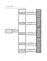
Page 26: ...22 3 6 LCD Operation The entire LCD structure is demonstrated in the diagram below ...

Page 27: ...ing and input status or press OFF ESC to allow the UPS to bypass mode or shut down refer to section on Single UPS Operation Bypass Mode Bypass Mode IP 208 0V 50 0Hz IP 208 0V 50 0Hz OP 208 0V 50 0 Hz OP 208 0V 50 0 Hz Batt 273 0V 99 Batt 273 0V 99 Load 0 Load 0 Warning 01 3 6 2 Operation menu 3 6 2 1 Main menu 1 After pressing the UP or DOWN button at the home page the LCD will display five items ...

Page 28: ... according to the setting and input status NOTE The UPS may be turned on by simply pressing the ON ENTER button in the home page It s not necessary to enter the control menu to turn on the UPS b In AC mode or converter mode or battery mode the LCD will display Turn Off in the control menu If it is selected and confirmed the UPS will transfer to bypass mode or shut down NOTE The UPS may be turned o...

Page 29: ...the screen After the selec tion is confirmed the display will return back to the home page and the mute icon will be displayed Control Battery Mode Turn On Mute Batt Test IP 0 0V 0 0Hz Mute Yes OP 208 0V 50 0 Hz Para Unlock No Batt 245 0V 50 Load 100 Backup Time 10H 4 Para Unlock part numbers with parallel option only This item allows the UPS to startup with parallel function and only appears when...

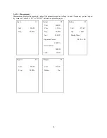
Page 30: ...c ity time etc Press the UP or DOWN button to explore the pages Input 1 5 Output 2 5 Battery 3 5 Volt 208 0V Volt 220 0V Curr 43 3A Volt 273 0V Freq 50 0Hz Freq 50 0Hz Cap 100 Inv 208 0V Dischg Time Apparent Power 00 00 00 6000VA Active Power 5400W Load 100 Bypass 4 5 Charger 5 5 Volt 220 0V Volt 273 0V Freq 50 0Hz Status On ...

Page 31: ... UPS Model XXXX Hot Standby 990 Minute DSP Ver XXXX Disable Batt Test Type MCU Ver XXXX Bypass Mute Short Time Unit Name Disable 10 Second XXXXXXXXX Batt Mute Manufacturer Disable XXXXXXXXX Fault Mute Disable 3 7 2 5 Setting This menu is used to configure the parameter settings or to do the calibrations NOTE Some settings will only be available in certain operation modes If the setting is not avai...
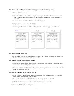
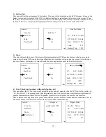
Page 32: ...PS will put the UPS into Bypass mode Then the UPS will go to bypass mode but with no output if it is turned off in AC mode NOTE The following items are only available in bypass mode 2 HighLoss V Set the acceptable high voltage for bypass Setting range is Bypass from rated Output Volt 11V to 276V The default value is 264V 3 LowLoss V Set the acceptable low voltage for bypass Setting range is Status...

Page 33: ...ing to the latest normal utility frequency If the utility frequency is in the range 46Hz to 54Hz then the output fre quency will be 50Hz If the utility frequency is in the range 56Hz to 64Hz the output frequency will be 60Hz ATO is the default setting 3 CVCF Enable or disable converter mode Enable The output frequency will be fixed at 50Hz or 60Hz according to setting of Freq The input frequency c...

Page 34: ... 1500 The maximum discharge time ranging from 0 to 1500 mi nutes When Dischg Protect is enabled the UPS will shut down to protect the battery after backup time arrives If Dischg protect is dis Battery abled then this setting is not functional The default value for this setting is 990 minutes DisChg Protect 2 Batt Test Type Enable 2 1 Short Time Battery test will last for a duration of 10 seconds 9...

Page 35: ...6 9V The default value is 0V Charger calibra tion is only available in bypass line converter mode NOTE Before making any charger output voltage adjustment first disconnect all batteries to obtain an accurate charger vol tage The adjustment should be suitable to the battery specifi cations or the battery may be destroyed Interface Description Hot standby Others Enable Hot standby function is enable...

Page 36: ... the battery capacity such as 7AH 9AH 10AH Backup Time 12AH 17AH 26AH 40AH 65AH 100AH and so on The default value is 9AH Factor Calibrate the displayed backup time by adjusting this Backup Time multiplier factor The formulation is listed below Displayed backup time Original backup time X Multiplier Batt Groups 1 factor Batt Cap 9AH The value of the default factor is 1 0 and can range from 0 5 to 2...

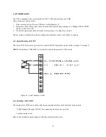
Page 37: ...sary communication software packages and interface cables are available as options 4 1 Serial Interface COM 3 The 9 pole SUB D connector pin contacts contains RS232 compatible signals Refer to Figure 11 on page 13 NOTE The interface COM RS232 is electrically isolated from primary UPS circuits Figure 14 Serial Interface COM3 4 2 Interface Slot COM The interface slot COM can be fitted with various o...

Page 38: ...PO connector pins is opened the output of the UPS is immediately switched off To restart the UPS the procedures outlined in the section Single UPS Operation must be followed The EPO circuit may be extended by connecting the normally closed switches in series between the EPO connector pins Activating opening any of the series switches will cause the UPS to shut off its output ...

Page 39: ... require maintenance by the user however battery maintenance is recommended in accordance with IEEE Recommended Practice for Maintenance Testing and Replacement of Valve Regulated Lead Acid VRLA Batteries for Stationary Applications IEEE Std 1188 1996 When the batteries expire trained battery service personnel must replace them A certified disposal recycling company should carry out disposal recyc...

Page 40: ...ses Released electrolyte is harmful to the skin and eyes and may be toxic A battery can present a risk of electrical shock and high short circuit current The following precautions should be observed when working on batteries Remove watches rings or other metal objects Use tools with insulated handles Wear rubber gloves and boots Do not short or bridge the battery terminals with any object Unplug a...

Page 41: ...switch off the input miniature circuit breaker of the UPS in case of fixed connections and switch off the circuit breaker of the external battery cabinet 4 Remove the UPS and external battery cabinet connections in the opposite sequence to that described in Installation 5 Note the date recharging was carried out on the packaging of the external battery cabinet 6 4 Cleaning NOTE Do not use scouring...

Page 42: ...ediately 3 In an emergency immediately disconnect the UPS from the connection to the utility external battery and output to avoid more risk or danger Alarm type LCD display Possible cause Remedy Warning 01 Batt Open 1 The battery is not connected 1 Connect the battery 2 The battery protection device 2 Replace or restore the protection is open device Warning 07 Over Charge 1 Battery numbers and set...

Page 43: ... if it is open Warning 33 Overload 3 The UPS is locked in bypass after Remove the overload shut down the Times an overload has occurred three UPS and restart it times in 30 minutes Warning 3A Maintain EMBS port is open or the maintain If the EMBS port is short circuited Open switch sensor connected to EMBS the warning will disappear port is triggered The UPS is transferred to bypass Warning 3F Par...

Page 44: ...for repair 2 The internal converter failed Fault 03 Bus Under The internal converter failed so that Contact the dealer to repair the DC bus voltage is too low Fault 04 Bus Unbalance 1 The load is abnormal Contact the dealer so that the internal positive and negative DC bus voltages are unbalanced 2 The internal converter failed Fault 11 Inv Start Fail The internal inverter failed so that Contact t...

Page 45: ...m Fault 36 OP I Unbalance The output current is extremely Contact the dealer to repair unbalanced between the parallel UPSs or there is an error in the parallel system Fault 41 Over Temp The internal temperature is too 1 Do not allow the ambient temp high and has reached the fault erature to exceed 40 C level shutdown 2 confirm that the fan is not blocked 1 environment may be too hot and is operat...

Page 46: ...e g bypass open or forbidden h frequency auto detect enable or disable i inverter short clear enable or disable 8 2 Output voltage calibration Before connecting the parallel cable s and the share current cable s between the UPSs in the parallel system turn on each UPS into the line mode or into the battery mode respectively Using a multimeter measure the output voltage of each UPS Make sure that t...

Page 47: ...Several seconds later each UPS will operate in bypass mode After a while the output relay on each UPS will close and now the parallel system can sup ply power to the loads via bypass b Check if the parallel information in the LCD display is as shown in the picture below If the parallel UPSs have been successfully set up then the LCD display will show Parallel Master Parallel Slave 1 or Parallel Sl...

Page 48: ...uzzer will beep once and the UPS will enter bypass mode or no output mode synchronously 8 6 Add one new unit into the parallel system a A UPS cannot be added into the parallel system while the system is running The load must first be re moved and then the parallel system shut down b Make sure the UPS that will be added to the parallel system is a parallel model and follow the instructions outlined...

Page 49: ...n Parallel Communication Port Connection CB 1 CB 2 Mains Power Distribution CB 3 CB Load Distribution CB CB Optional Output Circuit Breakers Share Current Cable Connection Parallel Communication Port Connection Wiring of two UPSs in parallel Wiring of three UPSs in parallel Figure 15 Wiring of two and three UPSs in Parallel ...

Page 50: ...out 6000VA 5400W Capacity 200 Vout 5400VA 4800W Rated Power Factor 0 9 Voltage VAC 208 V Factory Default 200 V 220 V 230 V 240 V Selectable Waveform Sinewave Voltage Regulation 1 Output Voltage THD 3 0 Linear Load 8 0 Non Linear Load Crest Factor 3 1 max Frequency Hz 50 60 Frequency Regulation 0 1 Hz Overload Transfer to Bypass Line Mode 100 110 10 min typical 110 130 1 min typical 130 1 sec typic...

Page 51: ...c Discharge IEC61000 4 3 Radiated Electromagnetic Field Immunity IEC61000 4 4 Electrical Fast Transient Burst Immunity IEC61000 4 5 Surge Immunity IEC61000 4 6 CS IEC61000 4 8 Power Frequency Magnetic Field IEC61000 2 2 Low Frequency Signal RoHS All units are RoHS compliant M E C H A N I C A L Length in mm 17 25 438 Height in mm 5 14 131 3U height Depth in mm 27 13 690 includes 2 75 70mm for I O w...

Page 52: ...t Weight lbs kg 142 64 5 Shipping Weight lbs kg 161 73 2 Percent Capacity Watts Number of Battery Cabinets 1 2 3 4 5 6 7 8 Runtimes are expressed in minutes Typical runtimes based on fully charged new batteries operating under typical load conditions Times estimated assuming a switch mode power supply Runtimes are affected by battery age ambient temperature site specific usage patterns and load co...

Page 53: ...S must be connected to a power source for 24 hours at least once every 4 months or every 2 months if the ambient temperature is more than 30 C 86 F Additionally POWERVAR s warranty on batteries applies only to Products that are continuously connected to AC mains power except during utility power outages Products that are regularly and intentionally disconnected from AC mains power will experience ...

Page 54: ... has a isolated input that the locally connected system can use to ShutDown the UPS 11 2 Installation in Sinergy III 6KVA UPS accessory slot To install the isolated contacts interface card 1 Turn off and unplug the UPS during the installation 2 Remove the slot cover plate two screws on the back of the unit 3 Firmly slide the card into the slot 4 Replace the two screws to secure interface card NOTE...

Page 55: ...lect N C Contact factory default JP1 jumpered 2 to 3 See Figure D6 N O Contact JP3 jumpered 1 to 2 A fifth signal will turn off the UPS inverter system This signal capability is provided for computer based systems that can signal when the operating system has been shut down and the UPS battery backup is no longer needed by the system This conserves any remaining battery charge for subsequent power...

Page 56: ...d Relay Contact Card Functional Diagrams Figure D8 Simplified Schematic of Interface Connections Function Pin AC FAIL NC 8 AC FAIL NO 9 LOW BATTERY NC 6 LOW BATTERY NO 7 BYPASS 1 ALARM 2 COMMON 5 SHUTDOWN 3 SHUTDOWN 4 ...

Page 57: ...port on the Isolated Contacts card in the UPS and the system monitor SYSMON card installed in the Meridian system Refer to the Nortel Meridian Documentation for details on configuring the system monitor for logging UPS infor mation Suggested references Meridian 1 System Installation and Maintenance PO842839 Meridian 1 XII System Messages PO842845 For POWERVAR Sinergy III Series UPS only Alarm cond...

Reviews: