background image

POWER SOURCE 

     WARNING

Do not connect sander to the power source until
all assembly steps have been completed. 

The motor is designed for operation on the voltage and 
frequency specified. Normal loads will be handled safely 
on voltages not more than 10% above or below specified 
voltage. Running the unit on voltages which are not within 
the range may cause overheating and motor burn-out. 
Heavy loads require that the voltage at motor terminals be 
no less than the voltage specified on nameplate.
•   Power supply to the motor is controlled by a single pole  
   locking rocker switch. Remove the key to prevent  


   unauthorized  use.

GROUNDING INSTRUCTIONS

     WARNING

Improper connection of equipment grounding conductor 
can result in the risk of electrical shock. Equipment should 
be grounded while in use to protect operator from 
electrical shock. 
•  Check with a qualified electrician if you do not 
  understand grounding instructions or if you are in doubt  
  as to whether the tool is properly grounded. 
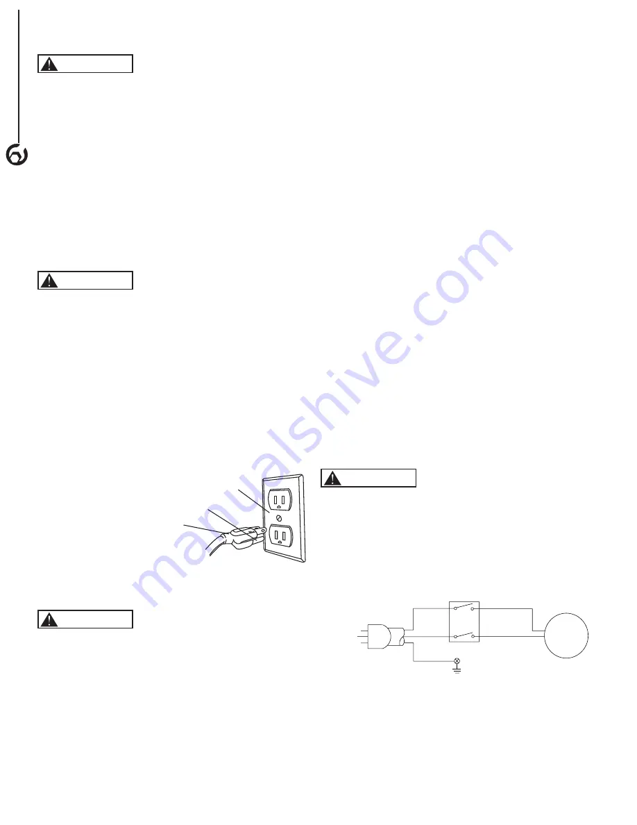
•  This tool is equipped with an approved cord rated at    
  150V and a 3-prong grounding type plug (see Figure 6)  
  for your protection against shock hazards. 
•  Grounding plug should be plugged directly into a  


  properly installed and grounded 3-prong grounding type  
  receptacle, as shown (see Figure 6). 

•  Do not remove or alter grounding prong in any manner.  
  In the event of a malfunction or breakdown, grounding   
  provides a path of least resistance for electrical shock. 

     WARNING

Do not allow fingers to touch the terminals of plug when 
installing or removing from outlet. 
•  Plug must be plugged into matching outlet that is  


  properly installed and grounded in accordance with all   
  local codes and ordinances. Do not modify plug  


  provided. If it will not fit in outlet, have proper outlet  


  installed by a qualified electrician.
•  Inspect tool cords periodically, and if damaged, have
  repaired by an authorized service facility.
•  Green (or green and yellow) conductor in cord is the
  grounding wire. If repair or replacement of the electric   
  cord or plug is necessary, do not connect the green (or  
  green and yellow) wire to a live terminal.

Properly Grounded Outlet

3-Prong Plug

Grounding Prong

Power Cord

Switch

Motor

4

ASSEMBLY

Figure 6

Figure 7

EXTENSION CORDS 

•  The use of any extension cord will cause some drop in  
  voltage and loss of power. 
•  Wires of the extension cord must be of sufficient size to  
  carry the current and maintain adequate voltage. 
•  Use the table to determine the minimum wire size  


  (A.W.G.) extension cord. 
•  Use only 3-wire extension cords having 3-prong 
  grounding type plugs and 3-pole receptacles which 
  accept the tool plug. 
•  If the extension cord is worn, cut or damaged in any    
  way, replace it immediately. 

Extension Cord Length

Wire Size…………….. A.W.G. 
Up to 25 ft…………… 16 gauge

NOTE:


Using extension cords over 25 ft. long is not 

recommended.

MOTOR

The sander is assembled with motor and wiring installed. 
The electrical wiring schematic is shown in Figure 9.
The permanently split capacitor motor has the following
specifications:
Horsepower (Peak HP) . . . . . . . . . . . . . . . . . . . . . . . . . 1/3
Voltage . . . . . . . . . . . . . . . . . . . . . . . .  . . . . . . . . . . . . 120
Amp. . . . . . . . . . . . . . . . . . . . . . . . . . . . . . . . . . . . . . . . 5.5
Hertz . . . . . . . . . . . . . . . . . . . . . . . . . . . . . . . . . . . . . . . .60
Phase. . . . . . . . . . . . . . . . . . . . . . . . . . . . . . . . . . . . .Single
RPM. . . . . . . . . . . . . . . . . . . . . . . . . . . . . . . . . . . . . . .3450

ELECTRICAL CONNECTIONS

     WARNING

All electrical connections must be performed by a qualified 
electrician. Make sure tool is off and disconnected from 
power source while motor is mounted, connected, recon-
nected or anytime wiring is inspected.
Motor and wires are installed as shown in wiring schemat-
ic (See Figure 7). Motor is assembled with approved,
3-conductor cord to be used at 120 volts.

The power lines are inserted directly onto the switch. The
green ground line must remain securely fastened to the 
frame to properly protect against electrical shock. The 
power supply to the motor is controlled by a single pole 
locking rocker switch.
• Remove the key to prevent unauthorized use.

Summary of Contents for BD4800

Page 1: ...1 11 0615 You will need this manual for safety instructions operating procedures and warranty Put it and the original sales invoice in a safe dry place for future reference Visit us on the web at www southerntechllc com 4 x 8 Woodworking Belt Disc Sander ...

Page 2: ... Unpackaging Tool Needed Mount Sander Attach Abrasive Disc Attach Table Attach Dust Collection Bag Power Source Grounding Instructions Extension Cords Motor Electrical Connections OPERATION 5 Basic Sander Operations Adjusting Belt Tracking Adjusting Belt Assembly Position Adjusting Table Angle Horizontal Belt Sanding with Work Stop Abrasive Belt Sanding Abrasive Disc Sanding Using Mitre Gauge Repl...

Page 3: ... be available for tool Three prong plug should be plugged directly into prop erly grounded three prong receptacle Extension cords should have a grounding prong and the three wires of the extension cord should be of the cor rect gauge Keep visitors at a safe distance from work area Keep children out of the work area Ensure your work shop is child proof Use padlocks master switches or remove switch ...

Page 4: ...ly 1 F Disc 1 G Wrench 4 mm 1 H Wrench 6 mm 1 Refer to Figures 2 5 CAUTION Do not attempt assembly if parts are missing Call the Customer service line to obtain replacement parts WARNING Do not operate sander until completely assembled Do not operate this tool until you have completely read and understood this manual ASSEMBLY 2 B A C D E F G H Figure 1 2 ASSEMBLY CAUTION Think safety Safety is a c...

Page 5: ...aluminum disc and press on firmly and evenly 4 Replace disc cover 2 1 3 Figure 2 ATTACH TABLE The included table is used with both the disc and belt To use the table with the disc Fig 3 1 Insert support rod 1 into base 2 Secure with bolt 3 on flat surface of rod 2 Position table assembly 4 on rod Make sure gap between table and disc is 1 16 1 5 mm or less Secure with bolt 5 3 Using a combination s...

Page 6: ...lified electrician Inspect tool cords periodically and if damaged have repaired by an authorized service facility Green or green and yellow conductor in cord is the grounding wire If repair or replacement of the electric cord or plug is necessary do not connect the green or green and yellow wire to a live terminal Properly Grounded Outlet 3 Prong Plug Grounding Prong Power Cord Switch Motor 4 ASSE...

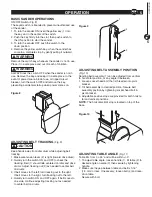
Page 7: ...ON and OFF to check the tracking Belt 1 should ride centered on idler and drive drums Adjust tracking nut 3 as needed to center belt on drums 3 If belt moves to the left turn tracking nut to the right If belt moves to the right turn tracking nut to the left 4 Quickly turn switch ON and OFF again If belt moves to one side continue adjusting tracking nut as needed to center belt on drums 1 3 1 2 1 2...

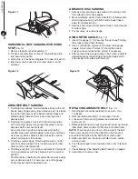
Page 8: ...OPERATION Figure 11 Figure 12 Figure 13 ABRASIVE DISC SANDING 1 Abrasive disc sanding is well suited for finishing small flat surfaces and convex edges 2 Move workpiece across down side left of abrasive disc Hold workpiece firmly with both hands keep fingers away from abrasive disc 3 Abrasive disc moves faster and removes more material at outer edge 4 For accuracy use mitre gauge USING MITRE GAUGE...

Page 9: ... screws 2 3 Remove old abrasive disc by peeling it from the aluminum disc Removng aluminum disc is not necessary 4 Clean aluminum disc 3 if necessary Use mineral spirits to remove old adhesive residue Select the de sired abrasive disc and apply to aluminum disc 5 Replace disc cover 1 2 4 3 3 1 2 7 Figure 14 Figure 15 ...

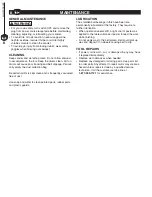
Page 10: ...ntly vacuumed free of dust Use soap and water to clean painted parts rubber parts and plastic guards MAINTENANCE 8 MAINTENANCE 8 LUBRICATION The shielded ball bearings in this have been are permanently lubricated at the factory They require no further lubrication When operation seems stiff a light coat of paste wax applied to the table will make it easier to feed the work while finishing Do not ap...

Page 11: ...nd other motors 2 Undersize wires or circuits too long 3 General overloading of power company s facilities 1 Reduce the load on the power line 2 Increase wire sizes or reduce length of wiring 3 Request a voltage check from the power com pany Motor overheats Motor overloaded Reduce load on motor Motor stalls result ing in blown fuses or tripped circuit break ers 1 Short circuit in motor or loose co...

Page 12: ...4 X 8 BELT DISC SANDER PARTS ILLUSTRATION 10 PARTS LIST 10 ...

Page 13: ...0 8 4 62 BD4800062 Cross Recessed Pan Head Screw M4x6 4 63 BD4800063 Retaining Ring 2 64 BD4800064 Set Screw M8x10 2 65 BD4800065 Pulley 1 66 BD4800066 Disc Guard 1 67 BD4800067 Socket Head Bolt M5x25 2 68 BD4800068 Flate Washer 5 ø10x1 2 69 BD4800069 Socket Head Bolt M5x10 2 70 BD4800070 FAN 1 71 BD4800071 Flat Washer 5 ø10x1 4 72 BD4800072 Socket Head Bolt M5x10 4 73 BD4800073 Dust Chute Plate 1...

Page 14: ...800130 Pin 10x20 1 131 BD4800131 Set Screw M8x10 2 132 BD4800132 Pulley 1 133 BD4800133 V Belt Z 570 1 134 BD4800134 Knob 1 135 BD4800135 Cross Recessed Pan Head Screw M6x10 1 136 BD4800136 Flat Washer ø4 1 137 BD4800137 Pointer 1 138 BD4800138 Miter Gauge 1 139 BD4800139 Slide Bar 1 140 BD4800140 Flat Washer 6 ø12x1 6 1 141 BD4800141 L Allen Wrench 6mm 90x55 1 142 BD4800142 L Allen Wrench 4mm 130...

Page 15: ...he proof of purchase documentation which includes a date of purchase POWERTEC will either repair or replace any defective part at our option at no charge to you The repaired or replacement unit will be covered by the same limited warranty for the balance of one year warranty period WHAT IS NOT COVERED This warranty applies to the original purchaser at retailer and may not be transferred This warra...

Page 16: ......

Reviews: