background image

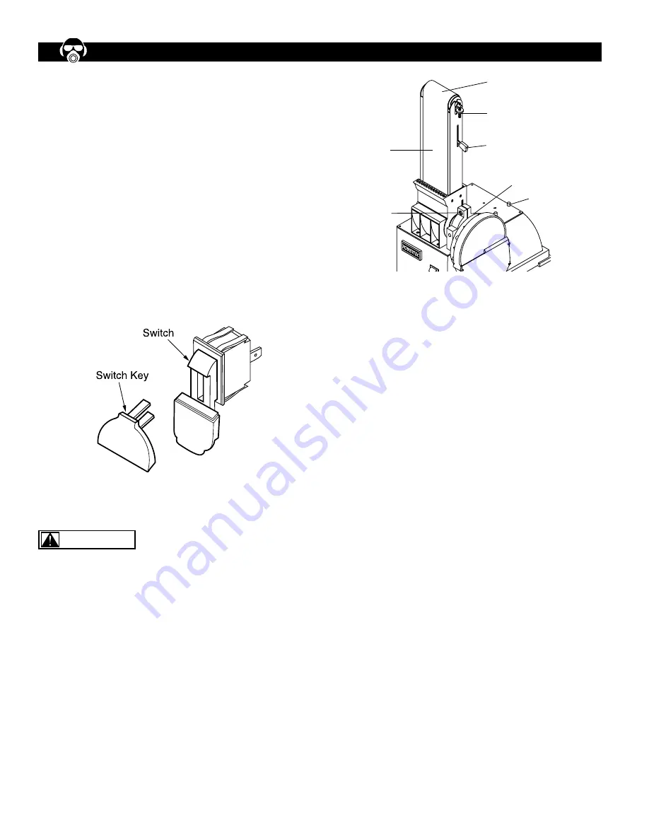
ON/OFF SWITCH

The ON/OFF switch is located in the front of Sander base. 

To turn the machine ON, pull the switch to the up position. 

To turn the machine OFF, push the switch to the down 

position.  


NOTE: When the machine is not in use, the machine 

should be locked in the “OFF” position to prevent unau-

thorized use.  


•  To lock the machine, turn the switch to the “OFF” 

   position and pull the key out. The switch cannot be 

   turned on without the key. 

•   If the key is removed when the switch is at the “On” 

   position, the switch can be turned off but cannot be 

   turned on again.  

•   To unlock, place the key into the slot on switch unit until  

   it snaps.  

ADJUST BELT TRACKING MECHANISM

Refer to Figure 9

Keep hands away from sanding belt, idler drum, drive 

drum, and any moving parts while conducting Belt 

Tracking Mechanism adjustment. 


•   To check sanding belt level, push the Tension Lever (b) 

   toward drive drum to tighten the sanding belt. 

•   To check the belt tracking, switch the machine ON and 

   OFF quickly. Watch the Sanding Belt (a) movement on 

   the Idler and Drive Drum. The Sanding Belt should 

   rotate without moving to the right and left.  

•   Use the Adjust Tracking Nut (c) to center the Sanding 

   Belt (a). If the Sanding Belt (a) keeps moving to the 

   right, turn the Adjust Tracking nut (c) to the left. If the 

   Sanding Belt (a) keeps moving to the left, turn the Adjust 

   Tracking nut (c) to the right. 

•   After each adjustment, switch the machine ON and OFF 

   quickly and check the Sanding Belt (a) movement again. 

   Repeat the procedures to adjust the belt tracking until 

   the Sanding Belt (a) is centered.

ADJUST BELT ASSEMBLY POSITION

Refer to Figure 9

•   The Sanding Belt Assembly (d) is designed to function 

   at any angle between horizontal and vertical position.  

   There are adjustable positive stops for both horizontal 

   and vertical positions. The Horizontal Stop is located on 

   top of the Base (h). It can secure the Sanding Belt 

   Assembly in horizontal position.

•   To change position, use L Wrench to loosen the Socket 

   Head Bolt (g) in the Pivot Bracket (f). The Pivot Bracket 

   is located between the Sanding Disc Assembly and The 

   Sanding belt Assembly. 

•   Position the Sanding belt Assembly (d) to the desired 

   angle and tighten the Socket Head Bolt (g) in the Pivot 

   Bracket (f).

ADJUST TABLE TILT ANGLE

Refer to Figure 10 

•   The table platform can be adjusted from 0 to 45 degree 

   (+/- 3°).

•   To adjust the table tilt angle, loose the Knob (i) on the 

   Tilt Angle Scale (k) under the Table Platform (j). 

•   Tilt the Table Platform (j) to the desired angel as 

   indicated by the Scale (k). Tighten the Knob (i).

•   Check that the distance between the Table Platform (j) 

   and the sanding surface is 1/16” or less. Do not allow 

   the sanding surface to touch any part of the Table 

   Assembly. If adjustment is necessary, loosen the Bolt 

   (l) that attach the Table Assembly to the Supporting Rod 

   and adjust the table platform position. Refer to ATTACH  

   THE TABLE TO USE WITH SANDING BELT section for 

   details.

Figure 8

Figure 9

OPERATION

6

     WARNING

d

g

a

c

b

f

h

Summary of Contents for BD4800 PRO

Page 1: ...H BUILT IN DUST COLLECTION 09 0909 QUESTION t t t You will need this manual for safety instructions operating procedures and warranty Put it and the original sales invoice in a safe dry place for future reference Visit us on the web at www southerntechllc com ...

Page 2: ... Abrasive Disc Attach the Table Assembly to Use with Sanding Disc Attach the Table Assembly to Use with Sanding Belt Attach Dust Collection Bag Power Source Grounding Instructions Extension Cords Motor Electrical Connections OPERATION 6 ON OFF Switch Adjust Belt Tracking Mechanism Adjust Belt Assembly Position Adjust Table Tilt Angle Belt Sanding in Horizontal Position Operate Sanding Belt Operate...

Page 3: ...tors can be injured Make your workshop childproof with padlocks master switches or remove switch keys to prevent any uninten tional use of power tools TOOL MAINTENANCE Turn the machine OFF and disconnect the machine from the power source prior to inspection Maintain all tools and machines in peak condition Keep tools sharp and clean for best and safest performance Follow instructions for lubricati...

Page 4: ... comes assembled as one unit Additional parts which need to be fastened to sander should be located and accounted for before assembling ITEM DESCRIPTION QUANTITY A Sander 1 B Dust Collection Bag 1 C Bag Clamp 1 D Mitre Gauge Assembly 1 E Table Assembly 1 F Disc 1 G Wrench 4 mm 1 H Wrench 6 mm 1 ASSEMBLY 2 Figure 1 B A C D E F G H ...

Page 5: ...able Assembly g onto the Supporting Rod d and position the table platform in level position Adjust the distance between the table platform and the Sanding Disc so it is 1 16 or less Do not allow the Sanding Disc to touch any part of the Table Assembly g Secure the Table Assembly g in position with the Bolt h Tighten the Bolt h against the flat surface of the Supporting Rod d Check that Table Assem...

Page 6: ...re 5 The plug must be plugged into an outlet that is properly installed and grounded in accordance with all local codes and ordinances Check with a qualified electrician or service personnel if these instructions are not completely understood or if in doubt as to whether the tool is properly grounded Do not modify plug provided If it will not fit in outlet have proper outlet installed by a qualifi...

Page 7: ...tor has the following specifications Horsepower Peak HP 0 5 Voltage 120 Amp 5 5 Hertz 60 Phase Single RPM 3450 ELECTRICAL CONNECTIONS Turn the switch off and disconnect the machine from power source before performing any repair or maintenance work Some electrical wiring and connection work must be performed by a qualified electrician in accordance with local regulations Scheme of the motor and ele...

Page 8: ...justment switch the machine ON and OFF quickly and check the Sanding Belt a movement again Repeat the procedures to adjust the belt tracking until the Sanding Belt a is centered ADJUST BELT ASSEMBLY POSITION Refer to Figure 9 The Sanding Belt Assembly d is designed to function at any angle between horizontal and vertical position There are adjustable positive stops for both horizontal and vertical...

Page 9: ...tective eye wear Keep fingers away from abrasive surface and any moving parts Use Table to securely position the workpiece during operation Use Sanding Disc for small object only Use sanding disc to sand flat or convex surface Use only the Down Side of the disc surface This is the area of the disc surface where the moving disc going downward It is to the left of the operator Move workpiece across ...

Page 10: ...ort Rod and Table Assembly REPLACE SANDING DISC ABRASIVE Refer to Figure 14 Remove Table Assembly Remove Support Rod Remove all screws m and remove the Disc Cover l Peel off the used Sanding Disc Abrasive Clean the surface of the Aluminum Disc Use Solvent to remove excessive residual adhesive if necessary Peel off the protective paper on the back of the New Abrasive Disc n With the adhesive side f...

Page 11: ...r to clean painted parts rubber parts and plastic guards LUBRICATION A light coat of paste wax on the work table will make it easier to feed the workpiece and prevent rust KEEP TOOL IN REPAIR If power cord is worn cut or damaged in any way do not operate the machine Replace any worn damaged or missing parts Use parts listed to order parts Any attempt to repair motor may create a hazard unless repa...

Page 12: ... circuit breakers 1 Reduce workload on the power supply 2 Check power supply for proper voltage 3 Use line cord of adequate size or reduce length of wiring 4 Reduce load on motor 5 Inspect the connection in motor for loose or shorted connection 6 Replace with correct fuses or circuit Motor overheats Motor overloaded Reduce load on motor Turn off the machine until motor cools down Machine slows dow...

Page 13: ...4 X 8 DISC BELT SANDER PARTS ILLUSTRATION 11 ...

Page 14: ... Chute 1 61 BD4800061 Flat Washer 4 ø9x0 8 4 62 BD4800062 Cross Recessed Pan Head Screw M4x6 4 63 BD4800063 Retaining Ring 2 64 BD4800064 Set Screw M8x10 2 65 BD4800065 Pulley 1 66 BD4800066 Disc Guard 1 67 BD4800067 Socket Head Bolt M5x25 2 68 BD4800068 Flate Washer 5 ø10x1 2 69 BD4800069 Socket Head Bolt M5x10 2 70 BD4800070 Impeller 1 71 BD4800071 Flat Washer 5 ø10x1 4 72 BD4800072 Socket Head ...

Page 15: ...0129 Motor 1 130 BD4800130 Pin 10x20 1 131 BD4800131 Set Screw M8x10 2 132 BD4800132 Pulley 1 133 BD4800133 V Belt Z 570 1 134 BD4800134 Knob 1 135 BD4800135 Cross Recessed Pan Head Screw M6x10 1 136 BD4800136 Flat Washer ø4 1 137 BD4800137 Pointer 1 138 BD4800138 Miter Guage 1 139 BD4800139 Slide Bar 1 140 BD4800140 Flat Washer 6 ø12x1 6 1 141 BD4800141 L Allen Wrench 6mm 90x55 1 142 BD4800142 L ...

Page 16: ...the date of purchase This warranty is specific to this tool Southern Technologies LLC reserves the right to repair or replace the defective tool at its discretion HOW TO OBTAIN SERVICE To obtain service for this POWERTEC tool you must return it freight prepaid to an authorized POWERTEC service center for bench top and stationary power tools You may obtain the location of the authorized service cen...

Page 17: ...direct indirect incidental or consequential damages Some states do not allow limitations on how long an implied warranty lasts and or do not allow the exclusion or limitation of incidental or consequential damages so the above limitations may not apply to you This warranty gives you specific legal rights and you may also have other rights which vary from state to state Southern Technologies LLC ma...

Page 18: ...Southern Technologies LLC 206 Terrace Drive Mundelein Illinois 60060 ...

Reviews: