


En
gli
sh
4 : 5.AESOP
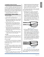
The aESOp connection can transport a single bidirec-
tional Fast Ethernet (iEEE 802.3u, 100 Mbit/s) control data
stream and two independent separate aES3 digital audio
monodirectional streams using one cat5 cable.
all k Series amplifier with the optional kaESOp board
installed are equipped with at least two rJ45 connectors,
each of them being a single aESOp port, capable of send-
ing and/or receiving data and audio.
if the amplifier has only two rJ45 plugs, these will be
on the front panel. if four plugs are present, the rear two
will be “primary” ports, while the two on the front panel are
“secondary” ports.
primary ports allow both data and aES3 streams; sec-
ondary ports are data-only ports, allowing Ethernet con-
nections only.
cat5 standard twisted pair cables shall be used for con-
nections up to 100 meters (328 ft). rJ45 pinout must comply
to Tia/Eia-568-B and adopt the T568B scheme pinout, as
show in
panel J, p. 12
.
For more details about networking and aESOp please
refer to the armonía pro audio Suite user guide.
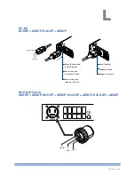
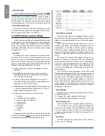
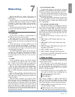
4 : 6.Loudspeaker connections
K6, K8, K10, K20
K2, K3
CLASS 3 WIRING
CLASS2 WIRING
Output terminals are hazardous: wiring connection
to these terminals require installation by an
instructed person and the use of ready made leads.
Take care to secure the output terminal
before switching the device on.
Two Neutrik NL4MD speakON connectors are located
on the rear panel, each of them being a single output to
loudspeaker.
pins 1+ and 2+ are physically bridged to the positive pole;
pins 1– and 2– are physically bridged to the negative pole.
in order to remain within safe operating conditions,
when using low impedance loads – i.e. 4 Ω or less (8 Ω or
less in bridge mode) –, connections must be made with a
four wire cable. use suitable wire gauges to minimize power
and damping factor losses in speaker cables.
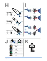
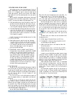
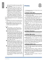
4 : 6.1. Bridge-tied load
Bridge-tied load connection can be achieved as de-
scribed in
panel i, p. 12
. in analog mode, only the input
of channel 1 needs to be wired: link channel 2 to channel 1
by means of the link pushbutton located on the rear panel.
When operating with digital inputs – i.e. aES3 and aESOp
– link the channels through armonía pro audio Suite software:
do not switch the link pushbutton.
CLASS3
WIRING
CLASS2
WIRING
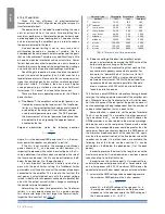
4 : 7.V Ext
The V Ext terminal is used to remotely manage the DSp
in k Series DSp amplifier and enable remote on/off.
k Series provided with a kaESOp board have a dedicat-
ed 2 pin phoenix connector McV 1,5/ 2-G-3,81 - 1803426
located near the rear Ethernet ports. k Series with the rS-
485 serial port implement the V Ext connection on pin 2 (pin
7) of the rJ45 rear connector (ref.
panel k, p. 12
).
When the V Ext port is powered by and external 12 V
Dc
(1 a max) power supply, the internal controller allows to con-
trol the DSp – if present – even without ac mains supply,
and allows serial communication – via rS-485 or ethernet
communication in kaESOp equiped models – for remote
on/off via the armonía pro audio Suite software.
4 : 8.RS-485 connection
k Series amplifiers without an optional kaESOp board
can be remotely controlled via an rS-485 connection.
remote connection data cables must have an 8p8c
modular plug – namely rJ45 plug – to be inserted in the
rear port labelled “DaTa pOrT”.
By plugging an rJ45 plug and selecting the unit’s remote
iD via the rotary trimmers, the amp is ready to be remotely
controlled. please note that iD numer 00 is not allowed.
The recommended arrangement of the connections is a
series of point-to-point (multidropped) nodes – i.e. a line or
bus. ideally, the two ends of the line should be terminated
with a resistor, typically 120 Ω for twisted pairs. powersoft
recommends the use of Ethernet cat5 straight through –
patch
– cables with pin/pair assignments Tia/Eia-568-B,
i.e. T568B, as shown in
panel J, p. 12
.
4 : 9.Ethernet connections
k Series amplifier platforms can be remotely controlled
via an Ethernet connection through a personal computer
and powersoft armonía pro audio Suite software.
powersoft recommends the use of Ethernet cat5
straight through –
patch
– cables with pin/pair assignments
Tia/Eia-568-B, i.e. T568B, as shown in
panel J, p. 12
.
24 | K Series
Summary of Contents for K2 DSP+AESOP, K3 DSP+AESOP
Page 4: ...Page intentionally left blank 2 K Series...
Page 8: ...A K2 K3 K2 DSP AESOP K3 DSP AESOP 465 32 2 496 456 5 9 482 439 44 32 6 K Series...
Page 88: ...Page intentionally left blank 86 K Series...
Page 89: ...Page intentionally left blank Specifications 87...
Page 90: ...Page intentionally left blank 88 K Series...
Page 91: ......