background image


Rev: 1.1 


Page 6 of 13 

1  Setting Up 


Grounding 

For the PowerMaster

®

 to properly stabilize and achieve the highest possible accuracy, the 

MTA15Z must be properly grounded.  Using the greed safety ground lead, insert the cable into 
the green “VOLTAGE DRIVE” (BOTTOM) female receptacle.  If using an alligator clip, connect to 
a known earth ground.  When using in a laboratory application, Powermetrix recommends the AC 
Plug to Safety Banana Plug Adapter (part# 10-340-0045).  This accessory allows the Auxiliary 
power, Auxiliary neutral, and ground to be easily terminated for a standard US three-prong AC 
wall outlet.   


Voltage Lead Connections 

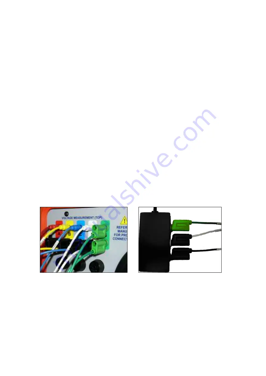
1.  Connect the Voltage Lead Set + Safety  Aux Power cable to the PowerMaster

®

.   

2.  Remove all alligator clips from the ends.   

3.  Separate the “MEASURE” and “RETURN” from the stackable banana jacks. 

4.  Insert the cables labeled “MEASURE” into the “VOLTAGE MEASURE” receptacles 

according to their color code. 

5.  Insert the cables labeled “DRIVE” into the “VOLTAGE DRIVE” receptacles according to 

their color code. 

6.  Insert the green lead with alligator clip into the “VOLTAGE DRIVE” receptacle.  Connect 

the alligator clip to a known earth ground. 

7.  Connect the AUX PWR and AUX NEU to a voltage source between 100-530VAC.   


Voltage cables from PowerMaster

®


Auxiliary power connected to voltage source 

(100-530VAC) 


WARNING

: Input voltage must be supplied from the Model 7332 or 7335 only.  Any other source 

voltage from the service or another device will cause damage to the MTA15Z that is 
not covered under the 1-year warranty.   


Summary of Contents for PowerMaster MTA15Z

Page 1: ...Rev 1 0 Page 1 of 13 MTA15Z PowerMaster Accessory Product Manual Revision 1 1...

Page 2: ...t not limited to the implied warranties of merchantability and fitness for a particular purpose TEC shall not be liable for errors omissions or inconsistencies which may be contained herein or for inc...

Page 3: ...Rev 1 1 Page 3 of 13 Table of Contents General Information 4 1 Setting Up 6 2 PowerMaster Procedure 9 2 1 With Site Selected 9 2 2 With No Site Selected Component Test 11 3 Error Messages 12...

Page 4: ...re saved as normal in the PowerMaster and will be downloaded using the Meter Site Manager 2 software Included Accessories Qty Part Description 1 10 340 3309 RS232 Communication Cable 1 10 340 0066 Pow...

Page 5: ...slow acting Case Pelican 1450 Dimensions 14 6 x 10 x 6 Weight 14 8 lbs 6 7 kg Warranty 1 year does not include fuses Technical Support For technical support please contact the factory at 865 218 5838...

Page 6: ...Ground Aux Power cable to the PowerMaster 2 Remove all alligator clips from the ends 3 Separate the MEASURE and RETURN from the stackable banana jacks 4 Insert the cables labeled MEASURE into the VOL...

Page 7: ...1 14 15 16 17 29 36 39 46 76 Removal To remove the probes push into the receptacle gently and now the probe will unlock for removal Communication and Power Connections 1 Connect the DB9 cable to RS232...

Page 8: ...ge of the lid 2 Remove the lid and place aside 3 Insert the meter into the appropriate socket 4 Rotate the MTA15Z in a vertical position so the case stands upright 5 For pulse detection use a Manual P...

Page 9: ...2 to create a new site STEP 3 In the Site Editor screen enter the Site ID meter form service and service type according to the Jumper Configuration Diagram STEP 4 Press F2 to select a meter in the dat...

Page 10: ...age 10 of 13 STEP 10 Select the setup then press F6 to continue STEP 11 After stabilization is complete and pulses are detected press F6 to continue STEP 12 After the test is complete press F6 to save...

Page 11: ...t the Meter Model and desired Service Type STEP 4 Enter the serial number MFG SN and alternatively the Kt value Press F6 to continue STEP 5 Hook up pulse pickup to meter AUX DIG on PowerMaster STEP 6...

Page 12: ...ervice type file that ends with M The PowerMaster cannot communicate with the MTA15Z Verify the following 1 Verify cables are connected according to Section 1 Setting Up Communication and Power Connec...

Page 13: ...cannot stabilize the currents and or voltages Attempt the following 1 Verify the green safety ground lead is connected to true earth 2 Verify the current leads are connected according to Section 1 Set...

Reviews: