


8
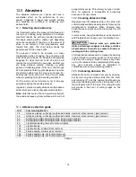
4. Continue to wrap abrasive in spiral fashion by
rotating drum with one hand and guiding strip
with the other. See Figure 6.
Successive windings of strip must
not have any
overlap.
They should be flush with previous
windings or with a slight gap between.
The last winding should have a 1/16 to 1/8 in.
gap, before insertion into inboard fastener (see
Figure 7).
Figure 6
5. Press inboard take-up lever (G, Figure 7) and
insert trailing end of strip as far as it will go. If
necessary, trim tapered end of abrasive strip.
6. Release inboard take-up lever to secure strip.
All abrasive strips will stretch over time as they are
used, and may stretch enough to allow the take-up
lever to reach its lowest position so that it cannot
maintain tension on the strip. If this occurs, follow
the above procedures to reset the take-up lever.
Figure 7
6.0
Electrical connections
All electrical connections must
be done by a qualified electrician in compliance
with all local codes and ordinances. Failure to
comply may result in serious injury.
The PM2244 Sander is rated at 115-volt power only.
The sander comes with a plug designed for use on
a circuit with a
grounded outlet
that looks like the
one pictured in
A
, Figure 8.
Before connecting to power source, be sure switch
is in
off
position.
It is recommended that the sander be connected to
a dedicated 20 amp circuit with circuit breaker or
fuse. If connected to a circuit protected by fuses, use
time delay fuse marked “D”.
Local codes take
precedence over recommendations.
6.1
GROUNDING INSTRUCTIONS
This machine must be grounded. In the event of a
malfunction or breakdown, grounding provides a
path of least resistance for electric current to reduce
the risk of electric shock. This tool is equipped with
an electric cord having an equipment-grounding
conductor and a grounding plug. The plug must be
plugged into a matching outlet that is properly
installed and grounded in accordance with all local
codes and ordinances.
Do not modify the plug provided - if it will not fit the
outlet, have the proper outlet installed by a qualified
electrician.
Improper connection of the equipment-grounding
conductor can result in a risk of electric shock. The
conductor with insulation having an outer surface
that is green with or without yellow stripes is the
equipment-grounding conductor. If repair or
replacement of the electric cord or plug is
necessary, do not connect the equipment-grounding
conductor to a live terminal.
Check with a qualified
electrician or service personnel if the grounding
instructions are not completely understood, or if
in doubt as to whether the tool is properly
grounded. Failure to comply may cause serious
or fatal injury.
Use only 3-wire extension cords that have 3-prong
grounding plugs and 3-pole receptacles that accept
the tool's plug.
Repair or replace damaged or worn cord
immediately.
2. Grounded, cord-connected tools intended for use
on a supply circuit having a nominal rating
less than
150
volts:
Summary of Contents for PM2244
Page 20: ...20 14 1 1 PM2244 Head Assembly I Exploded View ...
Page 21: ...21 14 1 2 PM2244 Head Assembly II Exploded View ...
Page 22: ...22 14 1 3 PM2244 Head Assembly III Exploded View ...
Page 26: ...26 14 2 1 PM2244 Conveyor Bed Assembly Exploded View ...
Page 29: ...29 15 0 Electrical Connections PM2244 Drum Sander ...
Page 31: ...31 This page intentionally left blank ...
Page 32: ...32 427 New Sanford Road LaVergne Tennessee 37086 Phone 800 274 6848 www powermatic com ...
Page 52: ...20 14 1 1 Ensemble tête I de la ponceuse PM2244 Vue éclatée ...
Page 53: ...21 14 1 2 Ensemble tête II de la ponceuse PM2244 Vue éclatée ...
Page 54: ...22 14 1 3 Ensemble tête III de la ponceuse PM2244 Vue éclatée ...
Page 58: ...26 14 2 1 Ensemble tapis du convoyeur PM2244 Vue éclatée ...
Page 61: ...29 15 0 Branchements électriques Ponceuse à tambour PM2244 ...
Page 63: ...31 La présente page a intentionnellement été laissée vierge ...
Page 87: ...23 14 1 1 Conjunto de cabeza I de PM2244 Vista desarrollada ...
Page 88: ...24 14 1 2 Conjunto de cabeza II de PM2244 Vista desarrollada ...
Page 89: ...25 14 1 3 Conjunto de cabeza III de PM2244 Vista desarrollada ...
Page 93: ...29 14 2 1 Conjunto de cabeza de lecho de banda transportadora de PM2244 Vista desarrollada ...
Page 96: ...32 15 0 Conexiones eléctricas Lijadora de tambor PM2244 ...
Page 98: ...34 ...
Page 99: ...35 ...
Page 100: ...36 427 New Sanford Road LaVergne Tennessee 37086 Teléfono 800 274 6848 www powermatic com ...