21
10. Place the aluminum knife gauge at the front
of the outfeed table (toward the rabbet
ledge) and repeat the process.
11. This test should be performed on all three
knives in the cutterhead, using the provided
gauge.
12. If any knife is either too high or too low at
one of its ends to correctly move the gauge
as described above, then the height and/or
parallelism of that knife in the cutterhead
needs to be adjusted. Proceed as follows.
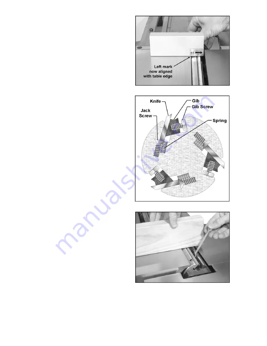
13. Slightly loosen the five gib screws (see
Figure 31) with an 8mm wrench. (NOTE:
The springs below the knife will cause the
knife to rise.)
14. Turn the jack screw(s) with a hex wrench;
clockwise to lower the setting of the knife in
the cutterhead, counterclockwise to raise
the setting of the knife.
15. Use the edge of a board to push the knife
back down so that it is flush against the jack
screws. See Figure 32. Tighten the gib
screws only enough to keep the knife in
position in the cutterhead. Do not fully
tighten.
16. Check the height of the knife again by using
the gauge at front and back of the outfeed
table. Make further adjustments to the jack
screw(s) as needed.
17. Repeat this process for each of the other
two knives in turn. Do not fully tighten gib
screws, only tighten them enough to keep
the knife in position.
18. For best results, knives should be set at
approximately .015" above the cutterhead.
Knife height should not vary more than .002-
.003" across the length of the cutterhead. All
three knives must be set at equal height in
the cutterhead and parallel to the outfeed
table across their length.
19. After all three knives are positioned properly
in the cutterhead and made snug, continue
tightening the gib screws. The gib screws
should be tightened in increments, to
prevent any distortion to the cutterhead or
buckling of knives. Begin tightening the gib
screws a little more on one knife. Start with
the center screw and work your way to the
ends. Do not fully tighten yet.
20. Rotate the cutterhead to the other two
knives in turn. Repeat step 20 for each
knife.
Figure 30
Figure 31
Figure 32
Summary of Contents for PJ-882
Page 35: ...35 Fence Assembly ...
Page 37: ...37 Outfeed Table and Base Assembly ...
Page 40: ...40 Infeed Table Assembly ...
Page 43: ...43 Stand Assembly ...
Page 44: ...44 Electrical Connections 1 Phase 230 Volt ...
Page 45: ...45 Electrical Connections 3 Phase 230 Volt ...
Page 46: ...46 Electrical Connections 3 Phase 460 Volt ...
Page 47: ...47 ...


