background image


PowerChord Group Limited 

Registered in England & Wales No. 9303518 

Registered Office: 1 Blythe Road, London W14 0HG 

 
Installation: 


1)


The PEEX tX Transmitter is a sealed device with no assembly required. 

2)


The device can be mounted using a number of attachment points suitable for cable 
ties.  If mounted at height, the PEEX tX should have a certified safety harness 
connected between permanent infrastructure and the safety loop point at the top of 
the PEEX tX. 


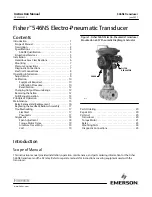
Figure 1.  The PEEX PWR-100154 Transmitter Attachment Points and Mounting Plate 

3)


Mounting to typical 50mm tubing and other fixed infrastructure can be achieved by 
attachment of a suitable clamp to the mounting plate at the rear of the PEEX tX.  The 
clamp should use countersunk M12 Hex socket bolts to ensure secure connection 
and avoid obstructing with the connection of the clamp to tubing. Please make sure 
that the M12 Hex socket bolts cannot enter further than 25mm into the mounting 
plate. 

4)


The PEEX tX is water resistant to the level of IP54.   

5)


To maintain the water resistance rating, the unit should only be mounted vertically 
with the cables entering from below.  Indoor use allows the device to be mounted in 
any orientation. 


Use: 


6)


The PEEX tX is powered from a mains electricity input supply of 100-240 VAC, 50-
60Hz and draws 0.25amps RMS. 

7)


To connect the PEEX tX to the power supply a powerCon True 1 NAC3FX-W 
connector must be fitted to a suitable mains cable capable of easily supporting a 

Multiple attachment 
points around the 
PEEX tX allow for 
secure mounting 
using cable ties. 
 

Safety harness 
attachment point. 
 

Mounting plate suitable 
for the attachment of a 
range of tube clamps to 
fix PEEX tX to lighting 
trusses and other typical 
infrastructure. M12 Hex 
socket countersunk bolts 
needed.  
 

Summary of Contents for PEEX PWR-100154

Page 1: ...d by the country specific regulations before enabling transmission There will be five main elements covered Radio Specifications Installation Use Status and Care Radio Specifications Approved for Use...

Page 2: ...W with antenna gain 6dBi FCC 15 407 a 1 i ii Radar detection No FCC 15 407 h 2 TPC No FCC 15 407 h 1 LSB No N A 5250 5350 MHz Available 20 MHz channels 52 56 60 64 Section in standard Maximum PSD 11 d...

Page 3: ...uding antenna gain e i r p 23 dBm no TPC ETSI EN 301 893 Table 2 Radar detection No ETSI EN 301 893 4 2 6 1 2 TPC No ETSI EN 301 893 4 2 3 1 2 LSB Yes ETSI EN 301 893 4 2 7 CAUTION The 5150 to 5250 MH...

Page 4: ...rdance with the instructions may cause harmful interference to radio communications However there is no guarantee that interference will not occur in a particular installation If this equipment does c...

Page 5: ...ry Canada Operation is subject to the condition that this device does not cause harmful interference Cet appareil est conforme la norme RSS 310 d Industrie Canada L op ration est soumise la condition...

Page 6: ...25 MHz doit tre conforme la limite de la p i r e iii le gain maximal d antenne permis pour les dispositifs utilisant la bande de 5 725 5 850 MHz doit tre conforme la limite de la p i r e sp cifi e pou...

Page 7: ...on and avoid obstructing with the connection of the clamp to tubing Please make sure that the M12 Hex socket bolts cannot enter further than 25mm into the mounting plate 4 The PEEX tX is water resista...

Page 8: ...an be inserted into either one of these sockets 11 If the Ethernet is to be looped through the PEEX tX to another device then suitable Ethernet cable capable of supporting 100base T networking can be...

Page 9: ...ut are not currently used 17 All other statuses are only available via the PEEX muX Multiplexer see separate document Care 18 To keep your PEEX tX clean use a damp cloth to remove any marks and then d...

Reviews: