background image

Willo Instruction Manual


Grounding 

The Willo cabinet should be grounded to the local earthing system using 2.5mm cable minimum. 

Battery Assembly 

1.  WARNING: Take all precautions to ensure that the risk of short circuit is eliminated 

during the assembly of the battery. Read the warning section in this manual. 

2.  The Willo cabinet can house up to 6 x 100Ah batteries in the lower 2 tiers. 
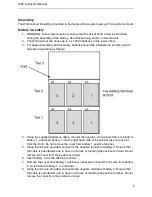
3.  For ease of assembly and for safety, batteries should be installed one at a time and in 

the same orientation as follows: 


4.  Using the supplied Anderson cable, connect the negative end (coloured blue or black) to 

battery 1, and insert battery 1 into the right hand side of the cabinet (as you look at it 
from the front). Do not remove the cover from battery 1 positive terminal. 

5.  Using the link wire provided, connect to the negative terminal of battery 2. Ensure that 

the cable is orientated so as to have no chance of touching the positive terminal. Do not 
remove the cover from the positive terminal. 

6.  Insert battery 2 into the cabinet as shown. 
7.  Remove the cover from battery 1 positive terminal and connect the link wire from battery 

2 -ve terminal to battery 1 +ve terminal. 

8.  Using the link wire provided, connect to the negative terminal of battery 3. Ensure that 

the cable is orientated so as to have no chance of touching the positive terminal. Do not 
remove the cover from the positive terminal. 

Summary of Contents for Willo

Page 1: ...Outdoor Integrated UPS Solution User Manual...

Page 2: ...N 3 Location 3 Mounting Securing 3 Grounding 4 Battery Assembly 4 AC Power Connections 6 Equipment Installation 6 UPS Installation 6 Operation 7 Starting Up 7 Switching Off 7 Maintenance 7 Appendices...

Page 3: ...he cabinet should only be performed by personnel trained in the risks involved 3 The Willo cabinet is designed to hold high capacity batteries Depending upon the configuration this may involve DC volt...

Page 4: ...away from any source of volatile gases 4 Do not place anything on top of the cabinet Mounting Securing 1 The cabinet may be secured to the base by driving 4xM10 bolts into a securing plate on a 430 x...

Page 5: ...ck to battery 1 and insert battery 1 into the right hand side of the cabinet as you look at it from the front Do not remove the cover from battery 1 positive terminal 5 Using the link wire provided co...

Page 6: ...the correct polarity and of the correct voltage usually 36V nominal 13 Push the Anderson connector through the void in shelf above Tier 2 into the top tier and connect the Anderson connections BATT1...

Page 7: ...e that it is not advisable to dissipate more than 200W within the cabinet as excessive temperature build up could arise diminishing battery life and affecting unit performance 2 Customer equipment can...

Page 8: ...intenance on the power distribution panel ensure that the AC supply feeding the Willo cabinet is disconnected Maintenance 1 Maintenance should only be carried out by competent persons and involves che...

Page 9: ...econds clamps the voltage and diverts the surge current to earth When the over voltage disappears the module automatically resumes the high impedance state Should the module be subject to sustained ov...

Page 10: ...not stop AC power from feeding the UPS This means the UPS internal chargers are active and producing DC Therefore the UPS inverter will only start to take power from the batteries and hence test them...

Page 11: ...Rating 230V Nominal 160V 295V input window Battery String 36V Battery Charger 2x 4 5A Weight 7kg DC Supply Option 24Vdc 2x 100W Notes 1 The DC outputs are isolated from each other and can be connected...

Page 12: ...DOC WILLO MANUAL REV 1 4 www powerinspired com...

Reviews: