power automation PA 8000 EL Installation Instructions Manual Download Page 61

3.8.1  PAMIO boxes and modules

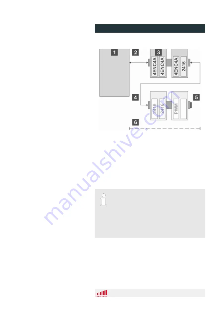
Fig. 37: PAMIO superbus schematic

1

control unit

2

PA superbus connection

3

PAMIO box with two analog axes modules

4

PA superbus connection

5

termination plug

6

max. chain length (14 PAMIO boxes/30 m (98 ft))

A PAMIO box consists of its housing, the PA superbus input and

output connectors as well as two plug-in-slots for I/O modules.

PAMIO boxes can be snapped onto DIN rails and plugged into

each other side by side or connected through optional cables. The

last box carries a termination plug.

Limited cable length
The limits for the I/O system are 31 I/O modules

(internal 2416 EL modules plus a maximum of 14

PAMIO boxes).

The maximum cable length from the control unit to the

last PAMIO box cannot exceed 30 m (98 ft). This has

to be considered as a maximum global length when

several PAMIO boxes are placed at different locations

and connected with interconnection cables.

I/O modules can be mounted where needed, without requiring bus

couplers. Each PAMIO module has its own watchdog timer for the

PA superbus, temperature and voltage monitoring as well as corre-

sponding LED displays on the front side.

Basic Description

PA 8000 EL CNC control unit

Design and function


24.09.2015 | 61


Summary of Contents for PA 8000 EL

Page 1: ...PA 8000 EL CNC control unit Installation instructions...

Page 2: ...ructions 2015 Power Automation GmbH Power Automation GmbH CNC Automatisierungstechnik Gottlieb Daimler Str 17 2 74385 Pleidelsheim Germany Telephone 49 7144 899 0 Fax 49 7144 899 299 email info powera...

Page 3: ...tive gear 14 2 6 Specific dangers 15 2 7 Safety devices 17 2 8 Machine safety 17 2 8 1 CNC ready signal Emergency stop interlocking 18 2 8 2 Power ok signal 19 2 9 Conduct in a dangerous situation and...

Page 4: ...4 2 Connection values 65 4 3 Operating conditions 66 4 4 Dimension sheet 67 4 5 Electromagnetic compatibility 68 4 6 Installation guidelines 69 5 Installation 73 5 1 Prerequisites and preparations 73...

Page 5: ...2 1 Module 2416 EL LEDs 91 8 3 Troubleshooting chart 93 9 Service and return process 95 9 1 Service 95 9 1 1 Service addresses 95 9 2 Spare parts 97 9 3 Return policy and procedure 97 9 4 Training 10...

Page 6: ...PA 8000 EL CNC control unit Table of contents 24 09 2015 6...

Page 7: ...d to facilitate basic understanding and may differ from the actual design of the control unit The enclosed manuals for the installed components apply together with this installation manual 1 2 Explana...

Page 8: ...ghlights a step as part of a procedure of instructions Highlights a state or an automatic process as a result of an instruction n Highlights single or unordered instructions and lists Additional symbo...

Page 9: ...additional options or due to the latest technical changes Apart from this the obligations agreed upon in the delivery con tract the general terms and conditions and the delivery conditions of Power Au...

Page 10: ...quirements for a machine tool operator emergency stop push button cycle start and stop push buttons jog plus and minus push but tons feed rate and spindle speed override pots and a number of auxiliary...

Page 11: ...the operating instructions created by him correspond to the current status of regulations and standards Whenever changes in regulations and standards occur instruc tions must be adapted accordingly n...

Page 12: ...to professional training knowledge and experience as well as profound knowledge of applicable regulations Skilled electrician A skilled electrician is able to carry out assigned work and to recognize...

Page 13: ...types cleared by Power Automation Prerequisite for the intended use of the control unit is proper configuration as described in the installation manuals provided by Power Automation WARNING Beware of...

Page 14: ...on manual and other installation man uals provided by Power Automation n The environment in which the control unit is installed may require users to wear additional personal protective gear Observe th...

Page 15: ...ents can cause danger to life n In the event of damage to insulation switch off the power supply immediately and have the defective parts repaired n Work on the electric system must be carried out onl...

Page 16: ...not throw batteries into fire or expose to high temperature Explosion hazard n Do not charge batteries Explosion hazard n Battery fluid leaking due to wrong usage may cause skin irrita tion Avoid cont...

Page 17: ...ation on required connections between the PA control unit and safety devices integrated into the CNC machine see the documentation provided by the machine s manufacturer Safety connector For informati...

Page 18: ...emergency stop safety chain All actions necessary for safety must be executed in the same way as when the Emergency Stop button is pushed n Properly integrate the CNC ready relay into the machine s em...

Page 19: ...ntal measuring systems use the corresponding entry in the control unit s drive configuration file DriveCfg ini to acti vate the monitoring of the correct range of these 5 V When the monitoring is acti...

Page 20: ...the other installation manuals provided by Power Automation 2 10 1 File backup A backup solution is preinstalled and configured It is neccessary to select and activate the backup function inside the C...

Page 21: ...fied USB memory sticks If you are not sure whether you can guarantee this please consider the usage of a USB Guardian software see http www trinit soft de usb waechter In Windows 7 the FBWF is already...

Page 22: ...tally hazardous substances or com ponents into the environment n Always properly dispose of environmentally hazardous compo nents substances in accordance with local law and regulations The following...

Page 23: ...CE Readability Of Labels Over the course of time labels may become dirty or nonreadable for any other reason Improper input vol tages applied due to readability of labels can damage the control unit K...

Page 24: ...readable or damaged the particular Windows licence will be void and can not be renewed For this reason the label has to be treated carefully A new operating system s licence can be ordered at Power A...

Page 25: ...s User HMIs based on own code scripts C Java or ActiveX must be tested by the customer itself The usage of compile cycles is the same as before Old CNC HMI Backups cannot be used in the current versio...

Page 26: ...PA 8000 EL CNC control unit Safety 24 09 2015 26...

Page 27: ...r 24 inputs and 16 outputs or 48 inputs and 32 outputs Machine tool axes are controlled by digital drives of the PA SDI range These drive units are connected via a single digital bus daisy chained fro...

Page 28: ...oring system The module status is displayed via 4 LEDs Fig 7 Overview connectors module 2416 EL 1 Output byte 2 X41 2 Output byte 1 X40 3 Status LEDs output byte 2 4 Status LEDs output byte 1 5 Power...

Page 29: ...ts 3 3 1 1 Input interfaces Fig 8 Input bytes 10 Input byte 2 X46 11 Input byte 1 X45 12 Input byte 3 X47 The inputs are grouped in bytes 8 signals Overview PA 8000 EL CNC control unit Design and func...

Page 30: ...terminal block n The conductor cross section of the wire must be 0 3 to 1 75 mm2 AWG 22 to 15 n The inputs are always referenced against the 0 V connector of the module X30 pin 3 Connection on page 3...

Page 31: ...bit pin 3 11 input bit pin 3 19 input bit pin 4 4 input bit pin 4 12 input bit pin 4 20 input bit pin 5 5 input bit pin 5 13 input bit pin 5 21 input bit pin 6 6 input bit pin 6 14 input bit pin 6 22...

Page 32: ...input path and therefore show the real state of the 24 V inputs n A HIGH input signal causes the corresponding LED to turn ON n A LOW input signal causes the corresponding LED to turn OFF Input Statu...

Page 33: ...5 k Input impedance 5 V input 8 6 k operating DC voltage OFF 24 V input 6 V max operating DC voltage ON 24 V input 18 V min operating DC voltage OFF 5 V input 1 2 V max operating DC voltage ON 5 V in...

Page 34: ...ed The inputs are located on bit 23 and 24 of the third byte of each 2416 EL module They are designed for 24 V encoder handwheels meeting the following spec ifications Special use of bits 23 and 24 of...

Page 35: ...ted on the 2416 EL module which is counting the track signals This avoids counting errors that could occur if the software was reading the tracks directly like standard I Os Prerequisites for the desc...

Page 36: ...byte 3 3 Power supply connector The ground of the power supply used for the hand wheel must be connected to the one of the power sup plies of the 2416 EL module connector X30 pin 3 Wiring Schematic P...

Page 37: ...al outputs 3 3 2 1 Output interfaces Fig 14 Output bytes 2 Output byte 1 X41 1 Output byte 2 X40 The outputs are grouped in bytes 8 signals Overview PA 8000 EL CNC control unit Design and function 24...

Page 38: ...uits Consider that the power supply cable for one output byte has to be chosen accordingly Each output has a nominal output capability of 1 A Nevertheless each output byte 8 signals is globally limite...

Page 39: ...0 output bit pin 3 3 output bit pin 3 11 output bit pin 4 4 output bit pin 4 12 output bit pin 5 5 output bit pin 5 13 output bit pin 6 6 output bit pin 6 14 output bit pin 7 7 output bit pin 7 15 out...

Page 40: ...e real state of the 24 V outputs n If the outputs are ON the corresponding LEDs are ON n If the outputs are OFF the corresponding LEDs are OFF n In case of a short circuit the output LED is OFF even i...

Page 41: ...ion per pin at 24 V for 1 5 A 0 45 W Output ON delay typical 100 s Output OFF delay typical 200 s Watchdog max 64 ms Short circuit output DC 0 7 2 5 A Delay time current limitation max 2 ms Isolation...

Page 42: ...s are realized on each 2416 EL module Fig 18 Module 2416 EL output schematic 1 Supplied from PCI Superbus board 2 Output supply input 15 12 5 3 Output n 1 4 Output n 5 Logic 6 Internal serial bus PA 8...

Page 43: ...nection Fig 19 Power supply connector 24 V DC Each of the 2416 EL modules needs a separate 24 V DC power supply for its DC outputs connector X30 Overview PA 8000 EL CNC control unit Design and functio...

Page 44: ...24 V power supply for output byte 1 Pin 3 0 V Pin 4 24 V power supply for output byte 2 Pin 5 24 V power supply for output byte 2 Property Value Unit Operating voltage 24 V DC Tolerance 15 0 12 5 Eff...

Page 45: ...power to be supplied independently to each byte in case of an emergency stop For proper load balancing across pins connections to all available pins per output byte are recommended Establish wire conn...

Page 46: ...r LEDs for diagnostic purposes Fig 21 Status LEDs 1 Status 2 Access 3 Bustest 4 Monitor For a detailed assignment of the LEDs states see Chapter 8 2 1 Module 2416 EL LEDs on page 91 Overview PA 8000 E...

Page 47: ...e to the control unit The control unit provides several RJ 45 connectors One or two are located on the PC interface panel Fig 22 1 and only intended for Ethernet connections The other RJ 45 connector...

Page 48: ...onnector of the control unit with the J1 connector of the first SDI drive 2 Connect additional SDI drives via the J1 and J2 connectors to each other and to the J2 connector of the first SDI drive as s...

Page 49: ...connectors 5 Ethernet connector RJ45 Hardware configuration subject to change Due to varying configurations of the mainboards pro duced by the suppliers the number and positions of USB serial and para...

Page 50: ...230 V AC or 4A MDL at 115 V AC Fig 25 Power supply connector Power supply properties Property Value Unit Voltage 115 240 V AC Tolerances 10 15 Frequency 50 60 Hz Maximum current at 115 V 4 A Maximum c...

Page 51: ...connector Sub D 15 Property Value Pins 15 Connector type sub D high density Gender female Pin X4 VGA Con nector 2 on page 51 Assignment 1 RED 2 GREEN 3 BLUE 4 not used 5 GND 6 RED GND 7 GREEN GND 8 B...

Page 52: ...ctor Pin Fig 27 Assignment 1 TMDS data 2 2 TMDS data 2 3 TMDS data 2 4 shield 4 TMDS data 4 5 TMDS data 4 6 Clock 7 Data 8 SYNC 9 TMDS data 1 10 TMDS data 1 11 TMDS data 1 3 shield 12 TMDS data 3 13 T...

Page 53: ...ol unit includes 3 standard USB 2 0 type A ports Fig 28 USB connectors Type A Property Value Pins 4 Connector type USB 2 0 Type A Max length 5 m 16 5 ft Pin USB 2 0 Connectors 4 on page 53 USB assignm...

Page 54: ...Inadvertent interchanging of the connector can cause control unit malfunctions and damages to the control unit and the attached drives n When setting up the wiring carefully observe the connectors pos...

Page 55: ...dard conforming distinction use wire sheathed in yellow green 3 6 Safety connector All PA 8000 EL models have two relays for safety functions The connector provides both a normally closed and a normal...

Page 56: ...6 1 Safety connector specification Property Value Form factor 6 pin removable screw plug Maximum contact load 1A 24V DC Fig 32 Safety connector pins Pin Fig 32 Assignment 1 Power ok common 2 Power ok...

Page 57: ...ion Result 5 V OK Ready relay active AND 12 V OK AND 12 V OK AND T 60 C 140 F NOTICE Damage to the control unit Voltage faults and or temperatures above the allowed specification can cause damage to t...

Page 58: ...voltage is within operation range n The operating temperature is below 55 C 131 F Logic Condition Result 5 V RMS OK Ready relay active AND Control unit ready AND T 55 C 131 F NOTICE Damage to the mac...

Page 59: ...port is specially marked as PA dongle port X20 This USB port is located on the bottom side of the control unit If the PA dongle is not connected to this port the PA software will not recognize the don...

Page 60: ...s connector located on the PCI interface board For further information see Chapter 3 8 1 PAMIO boxes and modules on page 61 or the PA Accessories installation manual The interface cable required to co...

Page 61: ...termination plug Limited cable length The limits for the I O system are 31 I O modules internal 2416 EL modules plus a maximum of 14 PAMIO boxes The maximum cable length from the control unit to the l...

Page 62: ...Cables of the following lengths can be ordered from Power Automation 2 m 6 5 ft 5 m 16 5 ft 10 m 33 ft 20 m 66 ft 25 m 82 ft see Chapter 9 Service and return process on page 95 Cable length Ensure th...

Page 63: ...ermination plug integrated Feature Value Specifications digital outputs 2 24 V DC The main characteristics for the digital inputs and outputs of the PAMIO 2416 are similar to the ones of the integrate...

Page 64: ...PA 8000 EL CNC control unit Design and function 24 09 2015 64...

Page 65: ...x 8 56 inch Weight 3 6 kg 7 94 lb 4 2 Connection values Property Value Unit Input voltage 115 240 V AC Tolerance 10 15 Frequency 50 60 Hz Maximum current at 115 V 4 A Maximum current at 240 V 2 A Maxi...

Page 66: ...ng 4 0 G Maximum acceleration operating 3 5 G Protection class EN 60529 IP20 NOTICE Functional defects The module casing does not provide sufficient protec tion against environmental influences Dust a...

Page 67: ...4 4 Dimension sheet Fig 39 dimension sheet PA 8000 EL CNC control unit Technical data 24 09 2015 67...

Page 68: ...ent of machines all met Standard Title Requirement Value EN 55011 2009 A1 2010 Limits of radio disturbance charac teristics interference voltage class B EN 55022 2006 A1 2007 interfering field strengt...

Page 69: ...interrupts Standard Title Requirement Value EN 61000 3 2 2006 Limits for harmonic current emis sions all met EN 61000 3 3 2008 4 6 Installation guidelines Electromagnetic compatibility EMC refers to...

Page 70: ...n The cable shield has to be laid extensively on a protected ground conductor rail directly after the cabinet entry and the fix ation of the shield with cable clamps n The isolation protected ground r...

Page 71: ...connection of the cable shield may be convenient if the conduction of a potential compensating line is not pos sible analog signals some mV respectively A are transferred foil screens static screens a...

Page 72: ...PA 8000 EL CNC control unit Technical data 24 09 2015 72...

Page 73: ...General requirements Prerequisites for installation are influenced by the con trol unit s required operating conditions and must also take into account the machine to be controlled Ensure that the co...

Page 74: ...it malfunctions Excessive strain on cables can cause malfunctions due to disruption of connections Install strain reliefs for all cable holes NOTICE For shielded cables it is necessary to apply the sh...

Page 75: ...a cabinet Fig 40 Mounting orientation n Always mount the control unit as shown in Fig 40 The dimensions are given in milimeters and in inches in parentheses Mounting Orientation PA 8000 EL CNC control...

Page 76: ...nd inputs outputs are located on the front side n Ensure that there is clearance of at least 50 mm 2 inches to allow accessibility to the connectors Fig 41 Front spacing Spacing PA 8000 EL CNC control...

Page 77: ...PC connectors is a grid for the air inlet n Ensure that there is clearance of 40 mm 1 6 inches at min imum for air circulation The cabinet fan provides internal air circulation for the control unit It...

Page 78: ...Fig 42 Top bottom spacing PA 8000 EL CNC control unit Installation 24 09 2015 78...

Page 79: ...ig 43 Electrical noise may influence the control unit s operation n Locate the control unit at least 300 mm 12 inches from areas which may transmit electrical noise Electrical noise may be caused by c...

Page 80: ...ditional metal shields n For all electrical installations follow the rules of VDE 0113 5 3 Installing digital I O The following chapters provide instructions and examples for installation of digital i...

Page 81: ...NC machine emergency stop chain Improper wiring and configuration of the safety relay may result in uncontrolled operation of the CNC machine and in consequence may lead to irreversible personal injur...

Page 82: ...the CNC Ready relay must be used to disconnect the machine s emergency stop safety chain All actions necessary for safety must be executed in the same way as when the Emergency Stop button is pushed...

Page 83: ...ernal temperature is too high n Use the contacts of the Power ok relay to switch off the main power supply of the CNC control unit unit to avoid any unex pected damages to the control unit The contact...

Page 84: ...PA 8000 EL CNC control unit Installation 24 09 2015 84...

Page 85: ...til control units are ready for assembly 6 2 Packaging The individual packages have been packed to match the transport conditions that can be expected The packaging has the function of protecting the...

Page 86: ...ry renew the packaging Property Value Unit Temperatures 20 60 C 4 140 F Humidity non condensing 80 Acceleration 4 0 G Additional requirements Packages may be marked with notes for storage which may ex...

Page 87: ...nsure order and cleanliness at the assembly site Loose parts and tools or parts and tools placed on top of each other are hazard sources If components have been removed ensure that they are properly m...

Page 88: ...hapter 7 3 Measures after mainte nance on page 88 Instructed person Make a backup of the data n For the exact procedure to make the backups see Chapter 2 10 Data safety on page 20 Skilled electrician...

Page 89: ...med only by specially trained per sonnel or only by Power Automation in which case special notice is given in the description of the individual faults n All work on the electrical system must be perfo...

Page 90: ...ct the control unit from the power supply 4 Immediately inform the person in charge of the equipment where the fault is located 5 Depending on the type of fault eliminate the fault or have it eliminat...

Page 91: ...6 EL module has four LEDs for diagnostic purposes Fig 47 Status LEDs 1 Status 2 Access 3 Bustest 4 Monitor The LEDs states are assigned the following status messages Overview PA 8000 EL CNC control un...

Page 92: ...5 seconds OR Warning 3 Outputs are overloaded for more than 15s On The 24 V output supply is correct AND There is no temperature error LED state Module status Off Default On Bustest between control un...

Page 93: ...trol unit to be sent to Power Automation follow the instructions given in Chapter 9 3 Return policy and procedure on page 97 Personnel n Qualified personnel n Skilled electrician 1 Properly shut down...

Page 94: ...97 Instructed person 003 Malfunction of the control unit Undetermined n Contact Power Automation in case of malfunctions relating to the con trol unit s startup and date time set tings n Do not open t...

Page 95: ...ce staff to log into your CNC This provides all the informa tion available on the machine They can check all the data like the PLC program machine parameters or the NC programs directly on the real sy...

Page 96: ...li Istanbul Turkey Tel 90 212 306 3280 Fax 90 212 306 3101 sales turkey powerautomation com Shenzhen Double CNC Tech Co Ltd 8th Floor WeiXinDa Building Bao Min Road 2 Xi Xiang Town Bao an District She...

Page 97: ...ines in your production facilities We suggest what crit ical stock may be required to ensure a minimum downtime of your machines Our specialists look for common parts to keep your inventory levels at...

Page 98: ...to the blue bar on the left side of the form These fields are for internal notes only and blocked 4 Send the completed form as an Excel file by email to rma powerautomation com to your local support s...

Page 99: ...Fig 48 RMA Form RMA Form PA 8000 EL CNC control unit Service and return process 24 09 2015 99...

Page 100: ...DU Other deliveries will be rejected The goods have to arrive within 4 weeks after the date of the approved RMA form 9 4 Training Having the best CNCs is one thing to bring out the best of it is the o...

Page 101: ...that fix the control unit inside the cabinet 7 Dismount the control unit Electronic components are considered special waste They must be properly disposed of Power Automation will accept the control u...

Page 102: ...PA 8000 EL CNC control unit Dismounting and decommissioning 24 09 2015 102...

Page 103: ...11 EC Declaration of Conformity EC Declaration of Conformity PA 8000 EL CNC control unit EC Declaration of Conformity 24 09 2015 103...

Page 104: ...Fig 49 EC Declaration of Conformity PA 8000 EL CNC control unit EC Declaration of Conformity 24 09 2015 104...

Page 105: ...12 Proof of change Version Change Date 1 Original Version 05 18 2015 Proof Of Change PA 8000 EL CNC control unit Proof of change 24 09 2015 105...

Page 106: ...PA 8000 EL CNC control unit Proof of change 24 09 2015 106...

Page 107: ...s 20 G General specifications 65 Ground screw 55 H Humidity 66 I Input Digital 29 Installation 73 Installation Guidelines 69 Instructed person 12 Intended use 13 IP protection class 74 L Labels 23 LED...

Page 108: ...tal input 34 Digital output 42 Power ok relay 83 Safety connector 59 SDI 47 Service 95 Service access 79 Service Addresses 95 Shield 79 Spacing 76 Spare Parts 97 Structural requirements 74 System prot...

Reviews: