background image

24

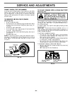
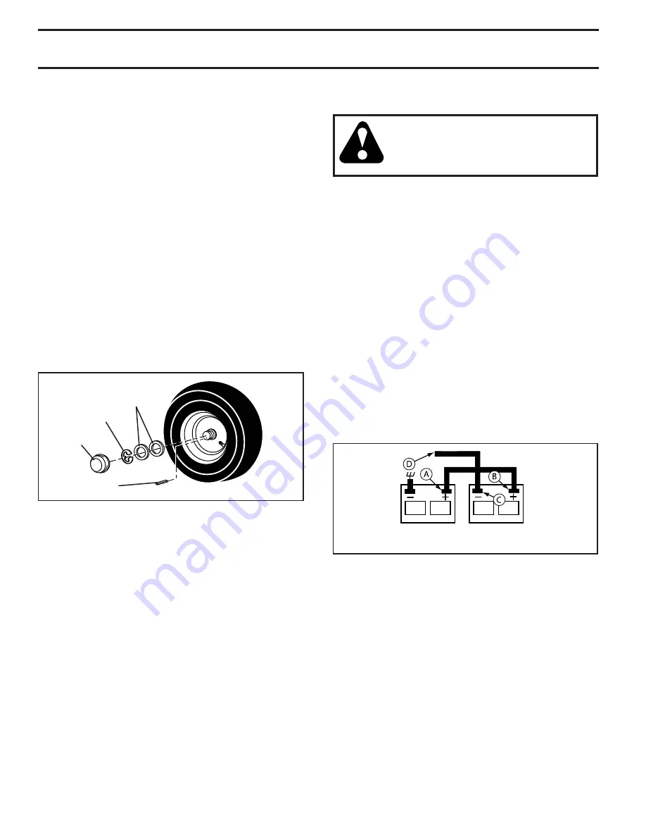
TO REMOVE WHEEL FOR REPAIRS 

(See Fig. 32)

•  Block up axle securely.
• 

Remove axle cover, retaining ring and washers to allow 

wheel removal (rear wheel contains a square key - Do 

not lose).

•  Repair tire and reassemble.
•  On rear wheels only:  align grooves in rear wheel hub 

and axle.  Insert square key.

FRONT WHEEL TOE-IN/CAM BER

Your new tractor front wheel toe-in and camber is set at the 

factory and is normal. The front wheel toe-in and camber 

are not adjustable.  If damage has occurred to affect the 

factory set front wheel toe-in or camber, contact a qualified 

service center.

FIG. 32

RE TAIN ING 

RING

WASH ERS

SQUARE KEY (REAR 

WHEEL ONLY)

AXLE COVER

TO START ENGINE WITH A WEAK BATTERY 

(See Fig. 33) 

WARNING

:

  Lead-acid batteries gen-

 er ate ex plo sive gases.  Keep sparks, 

flame and smoking ma te ri als away from 

bat ter ies.  Always wear eye pro tec tion 

when around batteries.

If your battery is too weak to start the engine, it should be 

recharged. (See "BATTERY" in the MAINTENANCE sec-

 tion of this man u al).
If “jumper ca bles” are used for emer gen cy starting, follow 

this pro ce dure:

IMPORTANT

:  YOUR TRACTOR IS EQUIPPED WITH A 12 

VOLT SYSTEM. THE OTHER VEHICLE MUST ALSO BE A 12 

VOLT SYSTEM. DO NOT USE YOUR TRACTOR BATTERY TO 

START OTHER VEHICLES. 

TO ATTACH JUMPER CABLES -

 •  Connect one end of the RED cable to the POSITIVE 

(+) terminal of each battery(A-B), taking care not to 

short against tractor chassis.

  •  Connect one end of the BLACK ca ble to the NEGA TIVE 

(-) terminal (C) of fully charged battery.

 •  Connect the other end of the BLACK cable (D) to good 

chassis ground,  away from fuel tank and bat tery.

TO REMOVE CABLES, REVERSE ORDER -

 •  BLACK cable first from chassis and then from the fully 

charged battery.

 •  RED cable last from both batteries.

FIG. 33

WEAK OR DEAD

BATTERY

FULLY CHARGED

BATTERY

•  Replace washers and snap retaining ring securely in 

axle groove.

•  Replace axle cover.

NOTE: 

To seal tire punctures and prevent flat tires due to 

slow leaks, tire sealant may be purchased from your local 

parts dealer. Tire sealant also prevents tire dry rot and 

corrosion.

SERVICE AND ADJUSTMENTS

Summary of Contents for 420408

Page 1: ...WAYS WEAR EYE PROTECTION DURING OPERATION Visit our website www poulan pro com WARNING Read this Manual and follow all Warnings and Safety Instructions Failure to do so can result in serious injury IMPORTANT MANUAL DO NOT THROW AWAY 420408 Rev 1 03076 ...

Page 2: ... dangerous Tires can lose traction with the ground and cause you to lose control of your tractor Do not operate the machine while under the influence of alcohol or drugs Watch for traffic when operating near or crossing roadways Use extra care when loading or unloading the machine into a trailer or truck Always wear eye protection when operating machine Data indicates that operators age 60 years a...

Page 3: ...ed equipment except at the hitch point Follow the manufacturer s recommendation for weight limits for towed equipment and towing on slopes Never allow children or others in or on towed equipment On slopes the weight of the towed equipment may cause loss of traction and loss of control Travel slowly and allow extra distance to stop V SERVICE SAFE HANDLING OF GASOLINE To avoid personal injury or pro...

Page 4: ... authorized service center department Wehavecompetent well trainedtechni cians and the proper tools to service or repair this tractor Please read and retain this manual The instructions will enable you to assemble and maintain your tractor properly Always observe the SAFETY RULES CUSTOMER RESPONSIBILITIES Read and observe the safety rules Follow a regular schedule in maintaining caring for and usi...

Page 5: ...g Wheel Steering Wheel Seat 1 Seat Steering Boot Steering Extension Shaft Steering Wheel Adapter Key s Slope Sheet 1 Oil Drain Tube For Future Use 1 Hex Bolt 1 Lock Washer 1 Large Flat Washer Steering Wheel Insert 1 Washer 1 Bolt ...

Page 6: ...y additional loose parts or cartons and remove BEFORE REMOVING TRACTOR FROM SKID TO CHECK BATTERY See Fig 1 Lift seat to raised position NOTE If this battery is put into service after month and year indicated on label label is located between terminals charge battery for minimum of one hour at 6 10 amps See BATTERY in Maintenance section of this manual for charging instructions For battery and bat...

Page 7: ... SLOT TAB ADJUSTMENT HANDLE FIG 3 Fig 4 TO ADJUST SEAT See Fig 4 Grasp adjustment handle and pull up slide seat to desired position and release adjustment handle NOTE You may now roll your tractor off the skid Follow the instructions below to remove the tractor from the skid WARNING Beforestarting read understandandfollow all instructions in the Operation section of this manual Be sure tractor is ...

Page 8: ...y and tightened securely All tires are properly inflated For shipping purposes the tires were overinflated at the factory Be sure mower deck is properly leveled side to side front to rear for best cutting results Tires must be properly inflated for leveling Check mower and drive belts Be sure they are routed properly around pulleys and inside all belt keepers Check wiring See that all connections ...

Page 9: ...entify safety inform ation about hazards which can result in death serious injury and or property damage DANGER indicates a hazard which if not avoided will result in death or serious injury WARNING indicates a hazard which if not avoided could result in death or serious injury CAUTION indicates a hazard which if not avoided might result in minor or moderate injury CAUTION when used without the al...

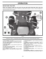
Page 10: ...arting the engine C PARKING BRAKE Locks clutch brake pedal into the brake position D THROTTLE CHOKE CONTROL Used for starting and controlling engine speed E ATTACHMENT CLUTCH LEVER Used to engage the mower blades or other attachments mounted to your tractor F IGNITION SWITCH Used for starting and stopping the engine G REVERSE OPERATION SYSTEM ROS ON PO SITION Allows operation of mower or other pow...

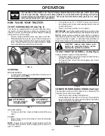
Page 11: ...ower blades move attachment clutch lever to disengaged position GROUND DRIVE To stop ground drive depress brake pedal all the way down ENGINE Move throttle control D between half and full speed fast position NOTE Failure to move throttle control between half and full speed fast position before stopping may cause en gine to backfire Turn ignition key F to STOP position and remove key Alwaysremoveke...

Page 12: ...sted when they are slightly off the ground when mower is at the desired cutting height in operating position Gauge wheels then keep the deck in proper position to help prevent scalping in most terrain conditions NOTE Adjust gauge wheels with tractor on a flat level surface Adjust mower to desired cutting height See TO AD JUST MOWER CUTTING HEIGHT in this section of manual With mower in desired hei...

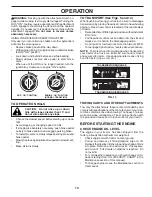
Page 13: ...king brake and brake pedal Slowly depress appropriate drive pedal to slowest set ting Make all turns slowly TRANSMISSION ENGAGED TRANSMISSION DISENGAGED ROS ON POSITION ENGINE ON POSITION NORMAL OPERATING 02828 WARNING Backing up with the attachment clutch en gaged while mowing is strongly discouraged Turning the ROS ON to allow reverse operation with the attachment clutch engaged should only be d...

Page 14: ...position The attachments and ground drive can now be used If the engine does not accept the load restart the engine and allow it to warm up for one minute using the choke as described above PURGE TRANSMISSION CAUTION Never engage or disengage freewheelleverwhiletheengineisrunning To ensure proper operation and performance it is recom mended that the transmission be purged before operating tractor ...

Page 15: ...the desired height Do not mow grass when it is wet Wet grass will plug mower and leave undesirable clumps Allow grass to dry before mowing Always operate engine at full throttle when mow ing to assure better mowing performance and proper discharge of material Regulate ground speed by se lecting a low enough gear to give the mower cutting performance as well as the quality of cut desired When opera...

Page 16: ...L RECOMMENDATIONS The warranty on this tractor does not cover items that have beensubjectedtooperatorabuseornegligence Toreceive full value from the warranty operator must maintain tractor as instructed in this manual Some adjustments will need to be made periodically to properly maintain your tractor At least once a season check to see if you should make any of the adjustments described in the Se...

Page 17: ...or is in the seat CHECK REVERSE OPERATION ROS SYSTEM When the engine is running with the ignition switch in the engine ON position and the attachment clutch engaged any attempt by the operator to shift into reverse should shut off the engine When the engine is running with the ignition switch in the ROS ON position and the attachment clutch en gaged any attempt by the operator to shift into revers...

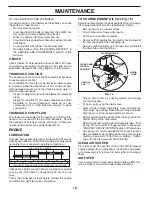
Page 18: ...30 20 0 20 30 40 F C 32 10 10 60 5W 30 10W30 oil_visc_chart4_e TO CHANGE ENGINE OIL See Fig 16 Determine temperature range expected before oil change All oil must meet API service classification SG SL Be sure tractor is on level surface Oil will drain more freely when warm Catch oil in a suitable container Remove oil fill cap dipstick Be careful not to allow dirt to enter the engine when changing ...

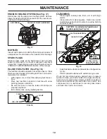
Page 19: ...ug fuel line sec tions Place new fuel filter in position in fuel line with arrow pointing towards carburetor Be sure there are no fuel line leaks and clamps are properly positioned Immediately wipe up any spilled gasoline Fig 19 Keep finished surfaces and wheels free of all gasoline oil etc Protect painted surfaces with automotive type wax We do not recommend using a garden hose or pressure washer...

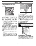
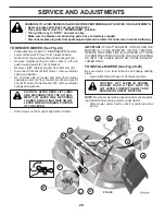
Page 20: ...rom chassis pin B and rear lift link C from rear mower bracket D remove retainer springs and washers CAUTION AFTER REAR LIFT LINKS ARE DISCONNECTED THE ATTACH MENT LIFT LEVER WILL BE SPRING LOADED HAVE A TIGHT GRIP ON LIFT LEVER WHEN CHANGING POSITION OF THE LEVER Slide mower out from under right side of tractor IMPORTANT IF AN ATTACHMENT OTHER THAN THE MOWER IS TO BE MOUNTED ON THE TRACTOR REMOVE...

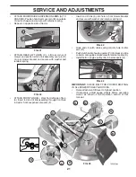
Page 21: ... side of tractor ATTACH REAR LIFT LINKS C Lift rear corner of mower and position slot in link assembly over pin D on rear mower bracket and secure with washer and retainer spring Insert end of link E into hole in front mower bracket and secure with washer and retainer spring J Hook end of clutch cable spring Q into hole in idler arm R Push clutch cable housing guide P into bracket slide collar L o...

Page 22: ...eight about 3 16 Test your adjustment by mowing some uncut grass and visually checking the appearance Readjust if necessary until you are satisfied with the results PRECISION SIDE TO SIDE ADJUSTMENT See Fig 27 With all tires properly inflated park tractor on level ground or driveway CAUTION Blades are sharp Protect your hands with gloves and or wrap blade with heavy cloth Raise mower to its highes...

Page 23: ...y remove belt upwards from transmission input pulley and over cooling fan blades D 4 Remove belt downward from engine pulley E 5 Slide belt toward rear of tractor off the steering plate F and remove from tractor BELT INSTALLATION 1 Install new belt from tractor rear to front over the steer ing plate F and above clutch brake pedal shaft G 2 Pull belt toward front of tractor and roll belt onto engin...

Page 24: ...charged See BATTERY in the MAINTENANCE sec tion of this manual If jumper cables are used for emergency starting follow this procedure IMPORTANT YOUR TRACTOR IS EQUIPPED WITH A 12 VOLT SYSTEM THE OTHER VEHICLE MUST ALSO BE A 12 VOLT SYSTEM DO NOT USE YOUR TRACTOR BATTERY TO START OTHER VEHICLES TO ATTACH JUMPER CABLES Connect one end of the RED cable to the POSITIVE terminal of each battery A B tak...

Page 25: ...ractor to an authorized service center for repair and or adjustment FIG 35 SERVICE AND ADJUSTMENTS TO REPLACE FUSE Replace with 20 amp automotive type plug in fuse The fuse holder is located behind the dash Fig 34 02603 SEAT PAN NUT POSITIVE RED CABLE NEGATIVE BLACK CABLE BOLT TERMINAL COVER REPLACING BATTERY See Fig 34 WARNING Do not short battery terminals by allowing a wrench or any other objec...

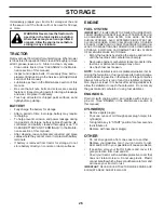
Page 26: ...FUELSYSTEMPARTSSUCH AS CARBURETOR FUEL FILTER FUEL HOSE OR TANK DURING STORAGE ALSO EXPERIENCE INDICATES THAT ALCOHOL BLENDED FUELS CALLED GASOHOL OR USING ETHANOLORMETHANOL CANATTRACTMOISTUREWHICH LEADSTOSEPARATIONANDFORMATIONOFACIDSDURING STORAGE ACIDIC GAS CAN DAMAGE THE FUEL SYSTEM OF AN ENGINE WHILE IN STORAGE Empty the fuel tank by starting the engine and let it run until the fuel lines and ...

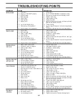
Page 27: ...ring 6 Check all wiring 7 Faulty ignition switch 7 Check replace ignition switch 8 Faulty solenoid or starter 8 Check replace solenoid or starter 9 Faulty operator presence switch es 9 Contact an authorized service center department Engine clicks but will not start 1 Weak or dead battery 1 Recharge or replace battery 2 Corroded battery terminals 2 Clean battery terminals 3 Loose or damaged wiring ...

Page 28: ...s improperly installed 9 Reinstall blades sharp edge down 10 Improper blades used 10 Replace with blades listed in parts manual 11 Cloggedmowerdeckventholesfrombuildup of grass leaves trash around mandrels 11 Clean around mandrels to open vent holes Headlight s not working if so equipped 1 Switch is OFF 1 Turn switch ON 2 Bulb s or lamp s burned out 2 Replace bulb s or lamp s 3 Faulty light switch...

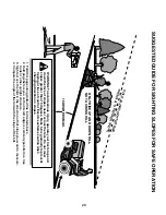
Page 29: ... never across the face Do not mow slopes greater than 15 degrees Make turns gradually to prevent tipping or loss of control Exercise extreme caution when changing direction on slopes 1 Fold this page along dotted line indicated above 2 Hold page before you so that its left edge is vertically parallel to a tree trunk or other upright structure 3 Sight across the fold in the direction of hill slope ...

Page 30: ...30 SERVICE NOTES ...

Page 31: ...31 SERVICE NOTES ...

Page 32: ...10 29 09 SR Printed in the U S A ...

Reviews: