background image

Safety • Assembly • Operation • Adjustment • Maintenance • Troubleshooting • Warranty

Warning: 

This unit is equipped with an internal combustion engine and should not be used on or near any unimproved forest-covered, brush-

covered or grass-covered land unless the engine’s exhaust system is equipped with a spark arrester meeting applicable local or state laws (if any). 
If a spark arrester is used, it should be maintained in effective working order by the operator. In the State of California the above is required by law 
(Section 4442 of the California Public Resources Code). Other states may have similar laws. Federal laws apply on federal lands. A spark arrester 
for the muffler is available through your nearest engine authorized service dealer or contact the service department, P.O. Box 361131 Cleveland, 
Ohio 44136-0019.

MTD LLC, P.O. BOX 361131 CLEVELAND, OHIO 44136-0019

PRINTED IN U.S.A.

READ SAFETY RULES AND INSTRUCTIONS CAREFULLY BEFORE OPERATION

IMPORTANT

OPERATOR’S MANUAL

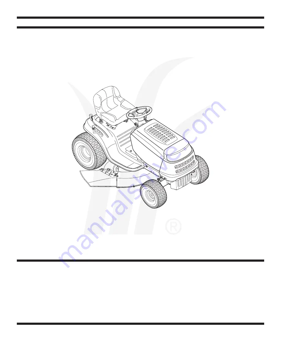
Transmatic Lawn Tractor — Models 760-779

01/06/2006

FORM NO. 769-01598B

Summary of Contents for 760-779

Page 1: ...ctive working order by the operator In the State of California the above is required by law Section 4442 of the California Public Resources Code Other states may have similar laws Federal laws apply on federal lands A spark arrester for the muffler is available through your nearest engine authorized service dealer or contact the service department P O Box 361131 Cleveland Ohio 44136 0019 MTD LLC P...

Page 2: ...est performance Please read and understand what it says Customer Support Slope Gauge 3 Safe Operation Practices 4 Setting Up Your Lawn Tractor 8 Operating Your Lawn Tractor 12 Adjusting Your Lawn Tractor 20 Maintaining Your Lawn Tractor 22 Off Season Storage Attachments 28 Safety Labels 29 Trouble Shooting 30 Warranty Back Page If you have difficulty assembling this product or have any questions r...

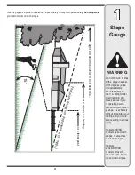
Page 3: ...alk behind mower on such a slope it is extremely difficult to maintain your footing and you could slip resulting in serious injury Operate RIDING mowers up and down slopes never across the face of slopes Operate WALK BEHIND mowers across the face of slopes never up and down slopes Use this page as a guide to determine slopes where you may not operate safely Do not operate your lawn mower on such s...

Page 4: ...en refuel such equipment on a trailer with a portable container rather than from a gasoline dispenser nozzle d Keep the nozzle in contact with the rim of the fuel tank or container opening at all times until fueling is complete Do not use a nozzle lock open device e Extinguish all cigarettes cigars pipes and other sources of ignition f Never fuel machine indoors g Never remove gas cap or add fuel ...

Page 5: ...g deck Contact with the blade s can amputate hands and feet 12 A missing or damaged discharge cover can cause blade contact or thrown object injuries 13 Stop the blade s when crossing gravel drives walks or roads and while not cutting grass 14 Watch for traffic when operating near or crossing roadways This machine is not intended for use on any public roadway 15 Do not operate the machine while un...

Page 6: ...urn slowly and gradually downhill if possible 2 Do not mow near drop offs ditches or embankments The mower could suddenly turn over if a wheel is over the edge of a cliff ditch or if an edge caves in 3 Do not try to stabilize the machine by putting your foot on the ground 4 Do not use a grass catcher on steep slopes 5 Do not mow on wet grass Reduced traction could cause sliding 6 Do not shift to n...

Page 7: ...damage e g excessive wear bent cracked Replace the blade s with the original equipment manufacturer s O E M blade s only listed in this manual Use of parts which do not meet the original equipment specifications may lead to improper performance and compromise safety 6 Mower blades are sharp Wrap the blade or wear gloves and use extra caution when servicing them 7 Keep all nuts bolts and screws tig...

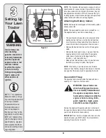
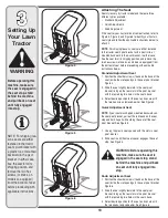
Page 8: ...d wire is secured to the positive battery terminal with a hex bolt and hex nut at the factory Make certain that the rubber boot covers the terminal to help protect it from corrosion Remove the hex bolt and hex nut from the negative cable Remove the black plastic cover if present from the negative battery terminal and attach the negative cable heavy black wire to the negative battery terminal with ...

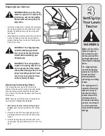
Page 9: ...d by grasping it between your thumb and index finger and rotating it clockwise WARNING The shipping brace used for packaging purposes only must be removed and dis carded before operating your riding mower WARNING The mowing deck is capable of throwing objects Fail ure to operate the riding mower without the discharge cover in the proper operating position could result in serious personal injury an...

Page 10: ...th applicable instructions below Standard Adjustment Seat 1 Position the shoulder screws found on the base of the seat inside the slot openings in the seat pivot bracket Figure 4 2 Slide the seat slightly rearward in the seat pivot bracket lining up the rear slots in the pivot bracket with the remaining two holes in the seat s base 3 Select desired position for the seat and secure with the two hex...

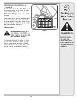
Page 11: ...s it to the cutting deck This will allow the clippings to discharge out of the discharge opening during operation See Figure 7 Tire Pressure WARNING Maximum tire pres sure under any circumstances is 30 psi Equal tire pressure should be maintained at all times The tires on your unit may be over inflated for shipping purposes Reduce the tire pressure before operating the tractor Recommended operatin...

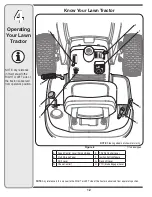
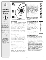
Page 12: ...ch Module C Shift Lever G Deck Lift Lever D Choke Control H PTO Blade Engage Lever NOTE Any reference in this manual to the RIGHT or LEFT side of the tractor is observed from operator s position If so equipped NOTE Any reference in this manual to the RIGHT or LEFT side of the tractor is observed from operator s position NOTE Steering wheel not shown for clarity ...

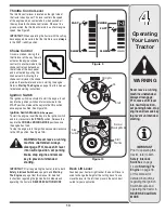
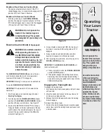
Page 13: ...sert key into the ignition switch and turn clockwise to the START position Release the key into the ON position once engine has fired See Figure 10A Ignition Switch Module If Equipped To start the engine insert the key into the ignition switch and turn clockwise to the START position Release the key into the NORMAL MOWING MODE position once the engine has fired To stop the engine turn the ignition...

Page 14: ...een reached release the lever into an appropriate notch to maintain that speed To slow the tractor s ground speed depress the clutch brake pedal and move the speed control lever rearward and release it into a notch NOTE Lawn tractors vary by model and are available with either a 6 or 7 speed control lever PTO Blade Engage Lever Found on the tractor s right fender the PTO blade engage lever is used...

Page 15: ...r Button at the top right corner of the key switch module The red indicator light at the top left corner of the key switch module will be ON while activated See Figure 12 4 Once activated indicator light ON the tractor can be driven in reverse with the cutting blades PTO engaged 5 Always look down and behind before and while backing to make sure no children are around 6 After resuming forward moti...

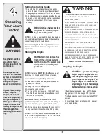
Page 16: ...he engine starts release the key It will return to the ON position IMPORTANT Do NOT hold the key in the START position for longer than ten seconds at a time Doing so may cause damage to your engine s electric starter 6 After the engine starts deactivate the choke control and place the throttle control in the FAST position NOTE Do NOT leave the choke control on while operat ing the tractor Doing so...

Page 17: ... NOTE When operating the unit initially there will be little difference between the highest two speeds until after the belts have seated themselves into the pulleys during the break in period WARNING Before leaving the operator s position for any reason disengage the blades place the shift lever in neutral engage the parking brake shut engine off and remove the key IMPORTANT When stopping the trac...

Page 18: ...ting the engine when traveling in reverse and if the operator leaves the seat Refer to Safety Interlock Switches on page 14 Using the Deck Lift Lever To raise the cutting deck move the deck lift lever to the left then place it in the notch best suited for your applica tion Refer to Setting The Cutting Height earlier in this section Mowing WARNING To help avoid blade contact or a thrown object inju...

Page 19: ...ick to the underside of the cutting deck preventing proper mulching of the clippings Do NOT attempt to mulch more than 1 3 the total height of the grass or approximately 1 1 2 inches Doing so will cause the clippings to clump up beneath the deck and not be mulched effectively Maintain a slow ground speed to allow the grass clippings more time to effectively be mulched Always position the throttle ...

Page 20: ...he front of the deck 4 Retighten the jam nut loosened earlier when proper adjustment is achieved Side to Side If the cutting deck appears to be mowing unevenly a side to side adjustment can be performed Adjust if necessary as follows 1 With the tractor parked on a firm level surface place the deck lift lever in the top notch highest position and rotate both blades so that they are perpendicular wi...

Page 21: ...nto stop Standard Seat To adjust the position of the seat loosen the two hex screws on the bottom of the seat Slide the seat forward or backward as desired Retighten the two screws See Figure 17 Knob Adjustment Seat if so equipped To adjust the position of the seat on models so equipped loosen the two knobs on the bottom of the seat See Figure 18 Slide the seat forward or backward as desired Retig...

Page 22: ... packed with your unit IMPORTANT Refer to the Engine Operator Owner Manual packed with your unit for information regarding the quantity and proper weight of motor oil Air Cleaner Service the pre cleaner if so equipped and cartridge air cleaner element as instructed in the Engine Operator Owner Manual packed with your unit Spark Plug s The spark plug s should be cleaned and the gap reset once a sea...

Page 23: ...gine pulley and idler pulley s Refer to Changing the Deck Belt on page 26 for detailed instructions 4 Looking at the cutting deck from the left side of the tractor locate the hair pin clip that secures the deck support rod on the rear left side of the deck See Figure 22 5 Remove the hair pin clip that secures the deck support rod and carefully remove the deck support from the deck lift arm 6 Repea...

Page 24: ...nstalling the battery follow these instructions to prevent the screwdriver from shorting against the frame IMPORTANT Never jump your tractor s dead battery with the battery of a running vehicle 1 Connect end of one jumper cable to the positive terminal of the good battery then the other end to the positive terminal of the dead battery 2 Connect the other jumper cable to the negative terminal of th...

Page 25: ...e its underside 2 Place a block of wood between the center deck hous ing baffle and the cutting blade to act as a stabilizer See Figure 24 3 Use a 15 16 wrench to remove the hex flange nut that secures the blade to the spindle assembly See Figure 24 4 To properly sharpen the cutting blades remove equal amounts of metal from both ends of the blades along the cutting edges parallel to the trailing e...

Page 26: ...d the engine pulley 4 Insert a 3 8 drive ratchet wrench set to loosen into the square hole found in the idler bracket on the left side of the deck s surface See Figure 26 5 Grasp the ratchet s handle and pivot it toward the front of the tractor to relieve tension on the belt 6 With belt tension relieved carefully remove the belt from around the left hand spindle pulley IMPORTANT Carefully allow th...

Page 27: ...27 6 Maintaining Your Lawn Tractor Figure 27 Figure 26 ...

Page 28: ...RNING Never store the machine or fuel container indoors where there is an open flame spark or pilot light such as on water heater furnace clothes dryer or other gas appliance Attachments Accessories The following attachments and accessories are compatible for Model Series 700 Lawn Tractors See the retailer from which you purchased your tractor an authorized MTD Service Dealer or phone 800 800 7310...

Page 29: ...ers Read and follow all instructions in this manual before at tempting to operate this machine Failure to comply with these instructions may result in personal injury When you see this symbol HEED ITS WARNING Your Responsibility Restrict the use of this power machine to persons who read understand and follow the warnings and instructions in this manual and on the machine ...

Page 30: ...n CHOKE position 5 Clean adjust gap or replace 6 Clean fuel line or replace fuel filter if so equipped 7 Crank engine with throttle in FAST position 8 Engage parking brake 9 Place throttle lever to FAST position Engine runs erratic 1 Push CHOKE control if so equipped in or move the throttle control out of the CHOKE position 2 Connect and tighten spark plug wire s 3 Clean fuel line fill tank with c...

Page 31: ...fouled faulty or gap too wide 2 Dirty air cleaner Mower will not mulch grass If Equipped 1 Place throttle control in FAST rabbit position 2 Do not mow when grass is wet wait until later to cut 3 Mow once at a high cutting height then mow again at desired height or make a narrower cutting path 4 Sharpen or replace blade 1 Engine speed too low 2 Wet grass 3 Excessively high grass 4 Dull blade Uneven...

Page 32: ...32 NOTES Use this page to make notes and write down important information ...

Page 33: ...33 NOTES Use this page to make notes and write down important information ...

Page 34: ...34 NOTES Use this page to make notes and write down important information ...

Page 35: ...arranty period stated above If the part fails during the period of warranty coverage the part will be repaired or replaced by MTD Consumer Group Inc according to subsection 4 below Any such part repaired or replaced under warranty will be warranted for the remainder of the period 2 Any warranted part that is scheduled only for regular inspection in the written instructions supplied is warranted fo...

Page 36: ... of the exterior finish due to use or exposure d Service completed by someone other than an authorized service dealer e MTD does not extend any warranty for products sold or exported outside of the United States its possessions and territories except those sold through MTD s authorized channels of export distribution f Replacement parts that are not genuine MTD parts g Transportation charges and s...

Reviews: