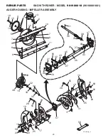
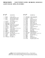
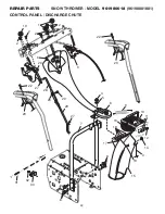
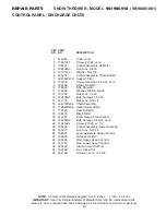
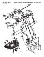
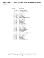
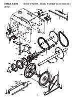
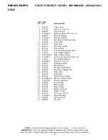
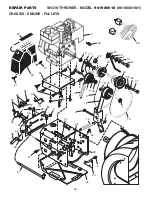
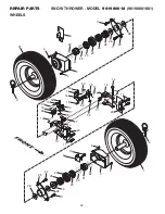
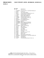
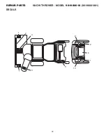
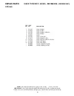
Poulan Pro 415332 Owner'S Manual Download Page 29

29

REPAIR PARTS


SNOW THROWER - MODEL  

961980018

  (96198001801)

CHASSIS / ENGINE / PULLEYS

NOTE:

  All component dimensions given in U.S. inches.     1 inch = 25.4 mm

IMPORTANT:

  Use only Original Equipment Manufacturer (O.E.M.) replacement parts.

Failure to do so could be hazardous, damage your snow thrower and void your warranty.

KEY   PART 

NO.    NO. 

DESCRIPTION

  1  414557 

 Spring, Traction Idler

  2  180522 

 Pulley, Idler (2-1/4)

  3     - - -  

 Engine, Tecumseh, Model Number 


 LH318SA (For engine service and 


 replacement parts, call Tecumseh


 Products at 1-800-558-5402)

  4  74780520 

 Screw, Hex Head  5/16-18 x 1-1/4

 5  150078 

 Screw

 6  59289 

 Washer, Flat

  7  166785 

 Nut, Jam, Lock  5/16-18

  8  175330 

 Pin, Idler Pivot

  9  407908 

 V-Belt, Traction Drive

 10  10040500 

 Washer, Lock  5/16

 11  17490508 

 Screw, Hex Washer Head

5/16-18 x 1/2

 12  410420 

 Impeller Arm Assembly

 13  85179 

 Retainer, Hairpin

 14  178828 

 Spring, Brake

 15  408007 

 V-Belt, Impeller Drive

 16  150406 

 Screw, Hex Head  3/8-16 x 1-1/4

 17  187786 

 Arm, Idler

 18  74780524 

 Screw, Hex Head  5/16-18 x 1-1/2

 19  175331 

 Bushing, Idler Pivot

 20  180523 

 Pulley, Idler (2-3/4)

 21  74610516 

 Screw, Hex Head  5/16-24 x 1

 22  409475 

 Spacer, Engine Pulley

 23  180478 

 Pulley, Engine, Traction Drive

 24  179157 

 Pulley, Engine, Impeller Drive

 25  400026 

 Washer, Flat  3/8

 26  850263 

 Washer, Lock  3/8

KEY   PART 

NO.    NO. 

DESCRIPTION

 27  851084 

 Screw, Hex Head  3/8-24 x 1-3/8

 28  155452 

 Guide, Belt

 29  192213 

 Belt Cover Assembly

(Includes Toolbox Cover)

 30  178830 

 Cover, Toolbox

 31  17490408 

 Screw, Hex Head  1/4-20 x 1/2

 32  402881 

 Bolt, Shoulder  5/16-18

 33  403096X004   Bellcrank Shifter

 34  198580 

 Clevis Pin

 35  405485 

 Arm, Auger Control

 36  191730 

 Locknut, Hex

 37  402856X004   Plate, Clutch

 38  187101 

 Link, Speed Control

 39 

416717X004


Bracket, Clutch

 40 

413429X479


Bracket, Traction

 41  700279 

 Hairpin, Cotter  3/32 x 1/2

 42  73930500 

 Locknut, Hex

 43  403097X004   Plate, Shifter

 44  17000616 

 Screw, Hex Head

 45  175324X479   Pivot Bracket, Impeller Idler Arm

 46  410877 

 Pan, Frame Bottom

 47  184471 

 Screw

 49  409346X428   Frame Assembly

 50  402685X428   Plate, Frame End

 51  406109 

 Shaft, Auger Control

 52  57079 

 Washer, Hardened

 53  35062 

 Key, Safety

 56  183528X428   Plate, Engine

 57  11050500 

 Washer, Lock, External Tooth

 58  198563 

 Power Cord

Summary of Contents for 415332

Page 1: ...ER Always Wear Eye Protection During Operation IMPORTANT MANUAL Do Not Throw Away WARNING Read the Owner s Manual and follow all Warnings and Safety Instructions Failure to do so can result in serious...

Page 2: ...hrown from the machine Operation 1 Do not put hands or feet near or under rotating parts Keep clear of the discharge opening at all times 2 Exercise extreme caution when operating on or cross ing grav...

Page 3: ...h transport speeds on slippery surfaces Look behind and use care when operating in reverse 13 Disengage power to the collector impeller when snow thrower is transported or not in use 14 Use only attac...

Page 4: ...parts and hardware you assemble must be tightened securely Use the correct tools as necessary to ensure proper tightness REMOVE SNOW THROWER FROM CARTON 1 Remove all accessible loose parts and parts b...

Page 5: ...ve control rod has the long loop on the end of the spring as shown 1 Slide rubber sleeve up rod and hook end of spring into pivot bracket with loop opening down as shown 2 With top end of rod position...

Page 6: ...thrower were overinflated at the fac tory for shipping purposes Correct and equal tire pressure is important for best snow throwing performance Reduce tire pressure to 14 17 PSI 19 24 5 N m AUGER CONT...

Page 7: ...Save this manual for future reference These symbols may appear on your snow thrower or in literature supplied with the product Learn and understand their meaning FORWARD PRIMER IGNITION KEY INSERT TO...

Page 8: ...ndle used for starting the engine Primer pumps additional fuel from the carburetor to the cylinder for use when starting a cold engine Choke control used for starting a cold engine MEETS A N S I SAFET...

Page 9: ...E CHOKE CONTROL See Fig 11 The choke control is located on the engine Use the choke control whenever you are starting a cold engine Do not use to start a warm engine To engage choke turn knob clockwis...

Page 10: ...are engaged the traction drive control lever will lock the auger control lever in the engaged position This will allow you to release your right hand from the handle and adjust the discharge chute di...

Page 11: ...o separation and formation of acids during storage Acidic gas can damage the fuel system of an engine while in storage To avoid engine problems the fuel system should be emptied before storage of 30 d...

Page 12: ...e control to the OFF position Allow the engine to warm up for a few minutes Engine will not develop full power until it has reached normal operat ing temperature WARM START RECOIL STARTER Follow the s...

Page 13: ...oningproperly LUBRICATION Keep your snow thrower well lubricated See LUBRICATION CHART MAINTENANCE LUBRICATION CHART SNOW THROWER Always observe the safety rules when performing any maintenance TIRES...

Page 14: ...MUFFLER Inspect and replace corroded muffler as it could create a fire hazard and or damage SPARK PLUG Replace spark plug at the beginning of each season or after every 100 hours of operation whicheve...

Page 15: ...ndinstall anew1 4 20x2 shoulder shearboltandspacer Install 1 4 20 lock nut and tighten securely CAUTION Do not substitute Use only original equipment shear bolts as supplied with your snow thrower 4 C...

Page 16: ...ses handles to rejoin the auger housing and frame assembly pull up on the auger belt and squeeze sides together above pulley so belt is fully seated in groove of pulley 11 Bring snow thrower completel...

Page 17: ...due to suspected carburetor problems take your snow thrower to a qualified service center Empty the fuel tank by starting the engine and letting it run until the fuel lines and carburetor are empty Ne...

Page 18: ...FULL position 1 Move choke to OFF position runs roughly 2 Blockage in fuel line 2 Clean fuel line 3 Stale fuel 3 Drain tank and refill with fresh clean fuel 4 Water in fuel 4 Drain fuel tank and carbu...

Page 19: ...19 SERVICE NOTES...

Page 20: ...8001801 AUGER HOUSING IMPELLER ASSEMBLY 6 6 5 9 9 12 7 7 8 6 11 57 10 13 4 14 16 15 36 37 50 47 42 42 44 27 27 43 43 46 38 45 41 40 39 34 32 49 19 48 51 33 35 56 30 31 19 19 55 26 10 22 25 20 18 58 25...

Page 21: ...SING IMPELLER ASSEMBLY NOTE All component dimensions given in U S inches 1 inch 25 4 mm IMPORTANT Use only Original Equipment Manufacturer O E M replacement parts Failure to do so could be hazardous d...

Page 22: ...22 REPAIR PARTS SNOW THROWER MODEL 961980018 96198001801 CONTROL PANEL DISCHARGE CHUTE 3 2 1 2 6 19 2 2 26 28 27 27 25 20 29 7 4 5 6 8 8 16 18 17 10 14 3 13 15 9 11 12 22 23 22 23 31 32 30...

Page 23: ...404770X428 Chute Assembly 16 178633X428 Deflector Assembly 17 179145 Seal Deflector 18 128415 Rivet Blind 19 414281 Knob Speed Control Lever 20 72270506 Bolt Carriage 5 16 18 x 3 4 22 74041024 Screw 1...

Page 24: ...REPAIR PARTS SNOW THROWER MODEL 961980018 96198001801 HANDLES 34 37 42 10 15 23 22 27 27 22 15 32 31 32 30 31 38 39 7 6 36 2 5 5 5 1 8 28 28 9 18 19 26 24 24 25 5 5 40 12 11 15 11 15 16 17 16 17 14 11...

Page 25: ...1 4 23 401940X479 Handle Tube Lower 24 180447 Sleeve Spring 25 180926 Spring Traction Drive 26 178669 Spring Auger Control 27 17000616 Screw Hex Head 3 8 16 x 1 28 412680 Bushing Pivot Lever 30 18334...

Page 26: ...26 REPAIR PARTS SNOW THROWER MODEL 961980018 96198001801 DRIVE 4 4 4 4 4 2 2 43 11 1 1 22 5 5 5 2 2 20 41 21 17 13 3 6 14 19 18 18 15 24 36 35 34 37 31 9 12 23 26 29 25 4 4 33 28 32 27 44...

Page 27: ...12 402187 Shaft Hex 13 402310 Pivot Rod Shifter 14 401732 Yoke Shifter 15 175344 Trunnion Bearing Assembly 17 178613 Hub Rubber Wheel 18 198176X479 Plate Rubber Wheel 19 74760514 Screw Hex Head 5 16...

Page 28: ...961980018 96198001801 CHASSIS ENGINE PULLEYS 6 19 17 10 21 22 23 2 3 4 6 42 8 9 12 13 15 27 26 25 24 18 7 20 14 5 40 46 44 49 50 51 52 35 34 33 38 37 39 43 11 32 32 36 36 44 45 41 30 29 31 31 11 11 1...

Page 29: ...6 18 x 1 1 2 19 175331 Bushing Idler Pivot 20 180523 Pulley Idler 2 3 4 21 74610516 Screw Hex Head 5 16 24 x 1 22 409475 Spacer Engine Pulley 23 180478 Pulley Engine Traction Drive 24 179157 Pulley En...

Page 30: ...ROWER MODEL 961980018 96198001801 WHEELS 4 4 31 2 8 3 4 4 32 34 30 32 30 15 18 17 19 13 20 11 10 21 33 22 23 24 25 26 28 28 29 27 27 28 28 26 29 25 24 23 22 33 19 21 16 20 11 11 11 11 14 7 10 10 34 9...

Page 31: ...w Hex Head 1 4 20 x 1 2 11 17490508 Screw Hex Head 5 16 18 x 1 2 12 405077 Link Steering Lever 13 193506X479 Lever Assembly Steering 14 182015 Pin Steering Lever 15 194944X008 Bellcrank 16 194939X008...

Page 32: ...32 REPAIR PARTS SNOW THROWER MODEL 961980018 96198001801 DECALS...

Page 33: ...te Deflector Control 11 415399 Decal LH Trigger 12 415398 Decal RH Trigger 415332 Owner s Manual English 415333 Owner s Manual French REPAIR PARTS SNOW THROWER MODEL 961980018 96198001801 DECALS NOTE...

Page 34: ...34 SERVICE NOTES...

Page 35: ...35 SERVICE NOTES...

Page 36: ...This Warranty does not apply to any product which has been sub jected to alteration misuse abuse improper assembly or installation delivery damage or to normal wear of the product 5 Exclusions Exclud...

Reviews: