background image

0000-GB zUSINFO / BA-EL ALLG.

GB

- z.42 -

iMPOrTanT! aDDiTiOnaL inFOrMaTiOn

see instruction handbook of the tractor
see price list and/or instruction handbook of the implement
to be measured

Consideration of rear mounted implement and front/rear combinations
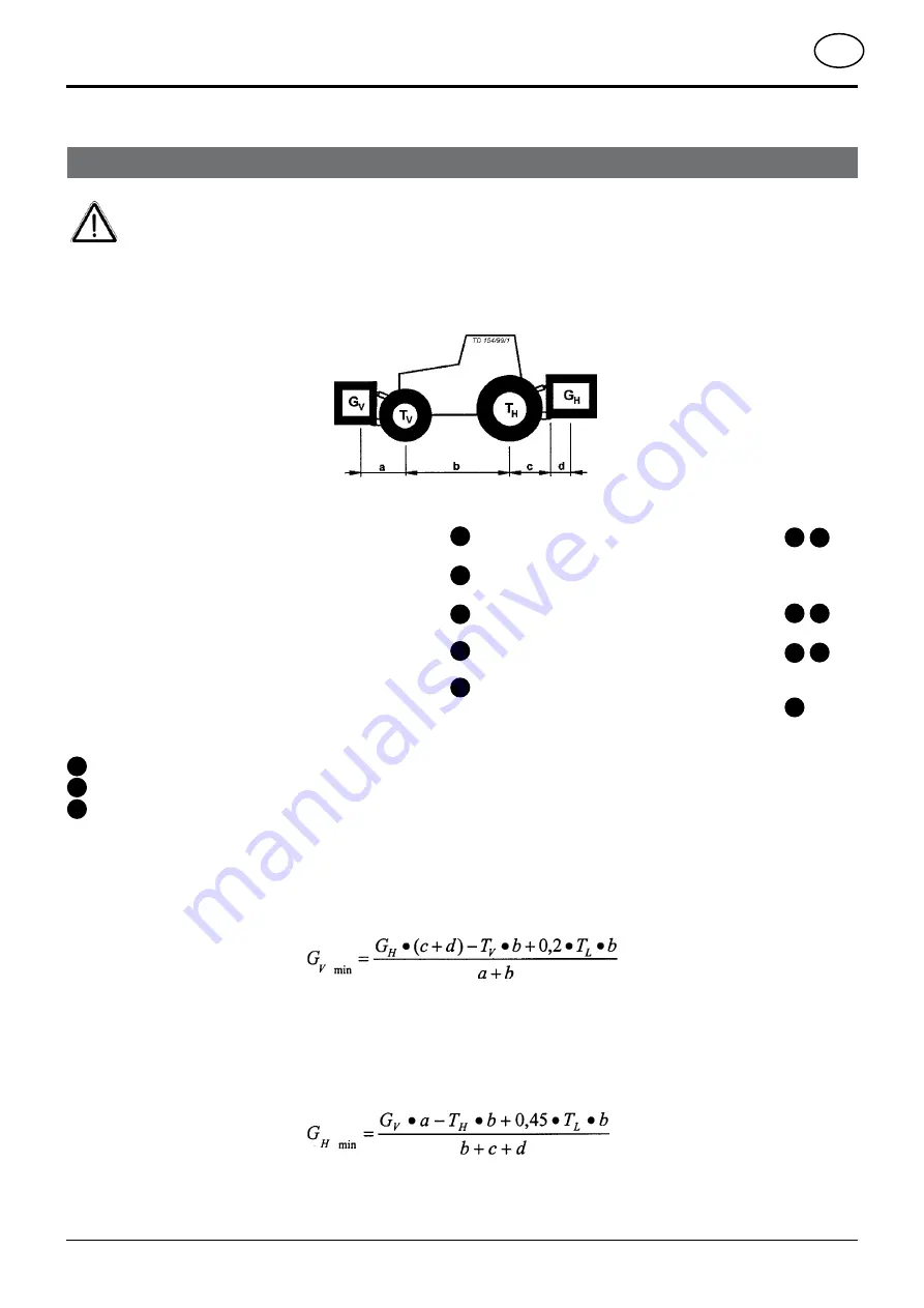
1. CALCuLAtIon oF MInIMuM BALLAstInG At tHe Front G

v min

Record the calculated minimum ballasting which is needed at the front of the tractor into the table.

Front mounted implement
2. CALCuLAtIon oF tHe MInIMuM G

H min

Record the calculated minimum ballasting which is needed at the rear of the tractor into the table.

For the calculation you need the following data:

T

L

 [kg]

T

V

 [kg]

T

H

 [kg]

G

H

 [kg]

G

V

 [kg]

unladen weight of tractor

front axle load of unladen tractor

rear axle load of unladen tractor

combined weight of rear mounted implement/rear 

ballast

combined weight of front mounted implement/front 

ballast

distance  from  centre  of  gravity  for 

combined front mounted implement/front 

ballast to front axle centre

Tractor wheelbase

distance from rear axle centre to centre 

of lower link balls

distance from centre of lower link balls 

to  centre  of  gravity  for  combined  rear 

mounted implement/rear ballast

a

 [m]

b

 [m]

c

 [m]

d

 [m]

2

3

1

1

1

1

1

2

2

2

3

3

1

3

2

Combination of tractor and mounted implement

The mounting of implements on the front or rear three point linkage shall not result in exceeding the maximum permissible weight, 
the permissible axle loads and the tyre load carrying capacities ot the tractor. The front axle of the tractor must always to be loaded 
with at least 20 % of the unladen weight of the tractor.
Make sure before buying an implement that these conditions are fulfilled by carrying out the following calculations or by weighing the 
tractor/implement combination.

Determination of the total weight, the axle loads, the tyre load carrying capacity and the necessary 

minimum ballasting

Summary of Contents for SERVO 45

Page 1: ...Nr 3425 4 3 2 02 5 4 6 29 0AGE 4RANSLATION OF THE ORIGINAL PERATING ANUAL Ihre Your Votre Masch Nr Fgst Ident Nr R 99 983 GB 80H 1 Plough SERVO 45 SERVO 45 PLUS SERVO 45 NOVA SERVO 45 NOVA PLUS SERVO...

Page 2: ...damage is damage caused by a machine and not to it An excess of Euro 500 is provided for such a liabilioty In accordance with the laws of product liability entrepreneurial property damages are exclude...

Page 3: ...have been made and that they are correct Hydraulic functions turnover cutting width adjustment have been demonstrated and explained Plough is set correctly to the tractor cutting width of 1st compone...

Page 4: ...of the ploughing component 19 ADDITIONAL DEVICES Setting the disk coulter 20 Spring loaded disk coulter 20 Pre ploughing implements 21 FEELER WHEELS Double feeler wheel 22 COMBI wheel Feeler and tran...

Page 5: ...ther relevant EU guidelines EU Declaration of Conformity see supplement By signing the EU Declaration of Conformity the manufacturer declares that the machine being brought into service complies with...

Page 6: ...usly then select the back position H In so doing the tractor s hydraulic unit will not be heavily loaded Position 2 the upper link 1 according to the tractor manufacturer s information Setting up for...

Page 7: ...1 Double action control unit 1 Double action control unit Preparations on the plough Mounting axle 965 mm 825 mm Use the correct mounting axle see also spare parts list Safety hint Forploughswith6she...

Page 8: ...the supportstand with linch pin K Insert pin only in the first hole Do not use holes in pos 2 9 otherwise support stand will be damaged when turning plough Lighting and Warning equipment When travell...

Page 9: ...ow VF Setting depends upon the inside distance between the tractor wheels RA and the set furrow width Further Information on the drawing point and backfurrow in chapter OPERATION Table B for SERVO PLU...

Page 10: ...dth Loosen both hexagonal screw SK Remove rear hexagonal screw Swivel anchoring console until the required furrow width is obtained and the hexagonal screw fits into one of the borings 1 2 3 4 5 Retig...

Page 11: ...intersecting point between the diagonal lines on the graph is the setting F Table for 965 mm Table for 825 mm Example A 512 mm B 1030 mm The intersecting point F lies between the lines 23 and 25 There...

Page 12: ...ed 180 Switch control unit ST to neutral 0 After some 5 seconds another turning procedure can be effected TD 65 92 48 s h 0 ST TD 65 92 25 90 Setting the plough gradient 11 The plough should sit as ve...

Page 13: ...urn spindle VF shorter Furrow width S2 correct Spindle is correctly set according to table See chapter PRESETTING THE PLOUGH Hydraulic furrow width adjustment SERVO PLUS However an additional double a...

Page 14: ...to the control servo valve via the upper link 1 or both the lower links The relevant impulse is then converted causing the lifting gear to lift or lower An example Securing upper link The plough penet...

Page 15: ...ploughing component swings away and up Remove the rest of the shear bolt Loosen hexagonal bolt 31 Swing ploughing component back into the working position Insert new shear screws and retighten both b...

Page 16: ...be approx 10 bar greater than the nitrogen pressure in the gas accumulator 43 Nitrogen pressure in the gas accumulator 43 Factory set 80 bar Pressure adjustment area of the hydraulic cylinder 40 90 t...

Page 17: ...t N until the mamometer shows the desired pressure has been reached e Close outlet valve remove filling device tighten gas filling plug and knock the lead mould plug if it exists back in 2 Increase pr...

Page 18: ...reat Cleaning the machine parts Take note Do not use a high pressure cleaner to clean bearings or hydraulic parts Danger of rust formation Lubricate the machine after cleaning and carry out a short tr...

Page 19: ...W UWS 10 20 mm for ploughing components of the type UW UWS WSS 4 Set the same measurement for gap B as for B1 The type of ploughing component is shown clearly on the manufacturer s plate Setting the p...

Page 20: ...ploughing blade tip The lengthwise fitting position is preselected by moving the carrier on the console Further fitting positions arise by swivelling the eccentric 50 180 Setting the disk coulter The...

Page 21: ...when ploughing in straw the pre ploughing implements should be set back as far as possible Leg deflector 60 Leg deflector which are fitted to the ploughing component serve to bend the stalks less when...

Page 22: ...983 9800 GB DoppelTastrad GB 22 FEELER WHEELS Double feeler wheel Theworkingdepthissetviathespindle 70 usingtheaccompanying ratchet Double feeler wheel fitted to the second last ploughing component...

Page 23: ...ty reasons do this from the tractor seat with the rope S With that swivel the control lever 90 position A The turning unit positions the plough vertically Remove bolts 3 swivel the support wheel conso...

Page 24: ...ole about 90 into working position and pin with the bolts 3 again A Secure bolts with linch pin 5 Cutting width adjustment for the servo plus hydraulically for the standard plough put the axle T3 in t...

Page 25: ...plough Using as feeler wheel Fix the depth Variant 1 Mechanical depth adjustment Move spindle 1 accordingly Move both spindles 2 accordingly Variant 2 Hydraulic depth adjustment Always from the tracto...

Page 26: ...via swivel cylinder on plough with hydraulic frame swing in 2 Lower plough and possibly hydraulic wheel to the ground 3 Bring wheel console into transport position Move pin 6 from pos T5 to pos T6 an...

Page 27: ...ts 3 swivel the support wheel console about 90 pin with the bolts 3 again A secure bolts with linch pin 5 Changing to working position 7 Bring cylinder or damper into work position Remove pin 7 Swivel...

Page 28: ...40 50 cm to the tractor wheel is also set with the strut 83 Transport position Pin strut 83 in the rear boring B With this the extension arm is swivelled in to the plough frame Working with a trailin...

Page 29: ...bearings Adjusting the amortisation effect With the arm two springs are delivered F1 F2 They reduce shocks wenn the trailing implement is penetrating Depending on the weight of the trailing implement...

Page 30: ...hole pattern A Setting positions A1 smallest distance A2 distance approx 30 cm A1 A3 distance approx 60 cm A1 A4 distance approx 90 cm A1 A5 greatest distance 2 Latching setting hole A Extension arm...

Page 31: ...draulically 81e Switch the servo valve briefly to lower to unlock the bolts TD65 92 85 82 81v 81e Working with a trailing implement For attachment a latching device is fitted to the trailing implement...

Page 32: ...rocedure 1 Fit chain holder H and control chain S 2 Fit chain adjuster L to extension arm 3 Set plough to the narrowest working width 4 Hook control chain S onto chain adjuster L and secure with pins...

Page 33: ...r being supplied Please enter the number onto the title page of this operating manual immediately after taking delivery of the implement Defined use of the plough according to the manufacturer s instr...

Page 34: ...Type Blades Component distance Frame height Cutting width Weight from kw hp SERVO 45 P 495 4 95 cm 80 cm 23 49 cm 1140 kg 80 110 SERVO 45 P 595 5 4 1 95 cm 80 cm 23 49 cm 1340 kg 96 130 SERVO 45 P 40...

Page 35: ...45 S P 695 6 5 1 95 cm 80 90 cm 23 49 cm 1790 kg2 SERVO 45 S P 402 4 102 cm 80 90 cm 25 53 cm 1350 kg SERVO 45 S P 502 5 4 1 102 cm 80 90 cm 25 53 cm 1550 kg SERVO 45 S P 502 5 102 cm 80 90 cm 25 53 c...

Page 36: ...saver UW UWS W WSS Double depth wheel Maize mulcher M1 M2 Subsoiler Smooth disk coulter Cutaway disk coulter Manure mulcher skim coulter DV 50 25 TD65 92 83 Warning sign Yellow reflex reflector for s...

Page 37: ...Suitable for all soils Especially for slopes shallow plougling Easy to pull Very good characteristics for newly ploughed fields The large slatted body Particularly suitable for heavy sticky soils Very...

Page 38: ...VA model as with the SERVO model however with an additional fully automatic overload safety device SERVO PLUS model A standard plough variation consisting of a b Four bar lever c d Hydraulic cutting w...

Page 39: ...GB Anhang Titelblatt _BA Allgemein GB Supplement...

Page 40: ...heap buy can sometimes be very expensive Be sure you purchase the Original with the cloverleaf sym bol Quality and precise fitting Operating safety Reliable operation Longer lasting Economy Guaranteed...

Page 41: ...bited a The transport of persons on the machine is not permitted b The machine may only be driven on public roads when in the position stipulated for road transport 7 Driving ability with auxiliary eq...

Page 42: ...t mounted implement front ballast distance from centre of gravity for combinedfrontmountedimplement front ballast to front axle centre Tractor wheelbase distance from rear axle centre to centre of low...

Page 43: ...he rear Record the calculated real and the permissible total weight given in the instruction handbook for the tractor into the table 5 CALCULATION OF THE REAL REAR AXLE LOAD TH tat Record the calculat...

Page 44: ...h requirements of EEC Directions 98 37 if applicable and to the other relevant EEC Directions __________________________________________________________________________ title and or number and date of...

Page 45: ...worden afgeleid Technische gegevens maten en gewichten zijn niet bindend Vergissingen voorbehouden Nadruk of vertaling ook gedeeltelijk slechts met schriftelijke toestemming van ALoIS P TTINGER Maschi...

Page 46: ...s P ttinger Maschinenfabrik Gesellschaft m b H A 4710 Grieskirchen Telefon 0043 0 72 48 600 0 Telefax 0043 0 72 48 600 511 e Mail landtechnik poettinger co at Internet http www poettinger co at Gebr P...

Reviews: