


8
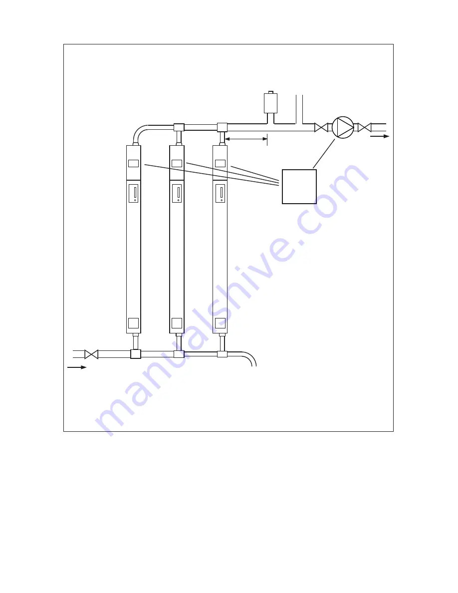
A typical plumbing schematic connecting 3 x 12kW boilers together.
NOTE:
The increase in pipework sizing to ensure proper flow through the boilers.
•
Ensure there are no restrictions in the heating circuit such as thermostatic radiator valves etc.
•
The expansion vessel has not been shown on this schematic.
•
For 2 x 12kW boilers, 28mm pipework flow and return is required.
•
A bypass must be fitted. Preference should be made for a 600 x 600 radiator.
•
FIGURE FOUR: THREE BOILER PLUMBING SCHEMATIC
AUTOMATIC AIR VENT
EXPANSION / SAFETY
RELIEF SYSTEM
SERVICE
VALVE
PUMP
ELECTRIC BOILER
FLOW
DRAIN VALVE
ELECTRIC BOILER
ELECTRIC BOILER
35mm PIPE
FLOW
36 LITRE/
MIN
28mm PIPE
FLOW
24 LITRE/
MIN
22mm PIPE
FLOW
12 LITRE/
MIN
35mm PIPE
FLOW
36 LITRE/
MIN
28mm PIPE
FLOW
24 LITRE/
MIN
22mm PIPE
FLOW
12 LITRE/
MIN
RELAY
SYSTEM
94970058
RETURN