


5
The installation must be carried out in accordance with the relevant requirements of:
The appropriate Building Regulations, either The Building Regulations, The Building Regulations
(Scotland) or Building Regulations (Northern Ireland)
The Water Fittings Regulations or Water Byelaws in Scotland.
IT IS THE INSTALLER’S RESPONSIBILITY TO ENSURE THAT THE INSTALLATION DOES NOT CONTRAVENE
THE REQUIREMENTS OF THE WATER SUPPLY REGULATIONS, BUILDING REGULATIONS OR LOCAL
AUTHORITY REGULATIONS.
The boiler must be installed by a qualified, competent tradesman who is aware of and will comply with
all relevant standards that are applicable: e.g. Building Regulations, the Local Authority Regulations,
the Water Supply Regulations and undertaking the relevant British Standards. The system must be
flushed in accordance with BS 7593 and in accordance with the supplied instructions and drawings
to ensure proper operation.
The boilers contain a very small amount of water, and so require a sufficient flow rate of water to
ensure proper operation. The 4kW and 6kW product requires a minimum flow of 6 litres/minute,
and the 9kW, 11kW and 12kW require a minimum flow of 12 litres/minute. Insufficient flow of water
through the boiler will cause nuisance trip outs. The maximum temperature differential between
input and output of the boiler must not exceed 14
0
C. If the temperature across the boiler exceeds
this then the flow rate is too low and will potentially damage the boiler. Set the flow rate to give 5 -
10
0
C across the boiler on full heat.
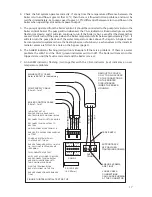
The output FLOW pipe at the TOP of the boiler is identified RED. The input RETURN pipe is located
at the BOTTOM. Ensure that the direction of flow is correct through the boiler after installation. Set
the pump on maximum flow rate.
Pipework connections on all models are 22mm.
Use standard size pipework. DO NOT SOLDER DIRECTLY ONTO THE BOILER TAILS. Push-on or
compression fittings are suitable for connecting directly onto the boiler tails. Fit a 22mm elbow to the
top of the boiler and after 100 – 150mm of horizontal pipework fit an automatic air vent, or connect
the expansion pipework on open vented systems to provide a route for air to vent. DO NOT FIT THE
AAV DIRECTLY ABOVE THE BOILER.
The electric boiler is suitable for operation in sealed or open vented systems. It is also suitable for
schemes such as heating only, Y plan, S plan, zone heating, under floor heating, micro-bore via a
manifold, etc. If you are unsure about your application regarding suitability of the boiler, please do
not hesitate to contact your local supplier or Potterton Gold directly.
The cost of installation can be reduced if the electric boiler is used for heating only. Use a direct
type cylinder with immersion elements and a time clock for the domestic hot water, then connect the
electric boiler directly to the heating circuit and control it by a programmable room thermostat. If the
radiator circuit has a continuously open route for the water flow, then a bypass is not required. The
boiler sizing is for heating only in this case and does not have to be increased to allow for domestic
hot water as well.
Ensure there is always an open route for the water to flow in any installation, to meet the required
minimum flow rate of the boilers and to allow for the pump over run. If an open route through the
heating circuit can not be guaranteed, then a bypass, fitted with an automatic bypass valve, must be
fitted which meets the required minimum flow rates for the boiler.
The bypass must have a minimum of either 2 metres of 22mm continuous pipework, or be routed
through a radiator with minimum dimensions of 600 x 600mm. Automatic pressure opening valves
must be used with the bypass circuit, ensure they are installed correctly as per the manufacturer’s
instructions. Gate valves are not suitable. DO NOT FIT A VALVE BETWEEN THE BOILER AND THE SAFETY
PRESSURE RELIEF VALVE OR EXPANSION RELIEF SYSTEM.
INSTALLATION - PLUMBING