background image


Page 9 

Step C:

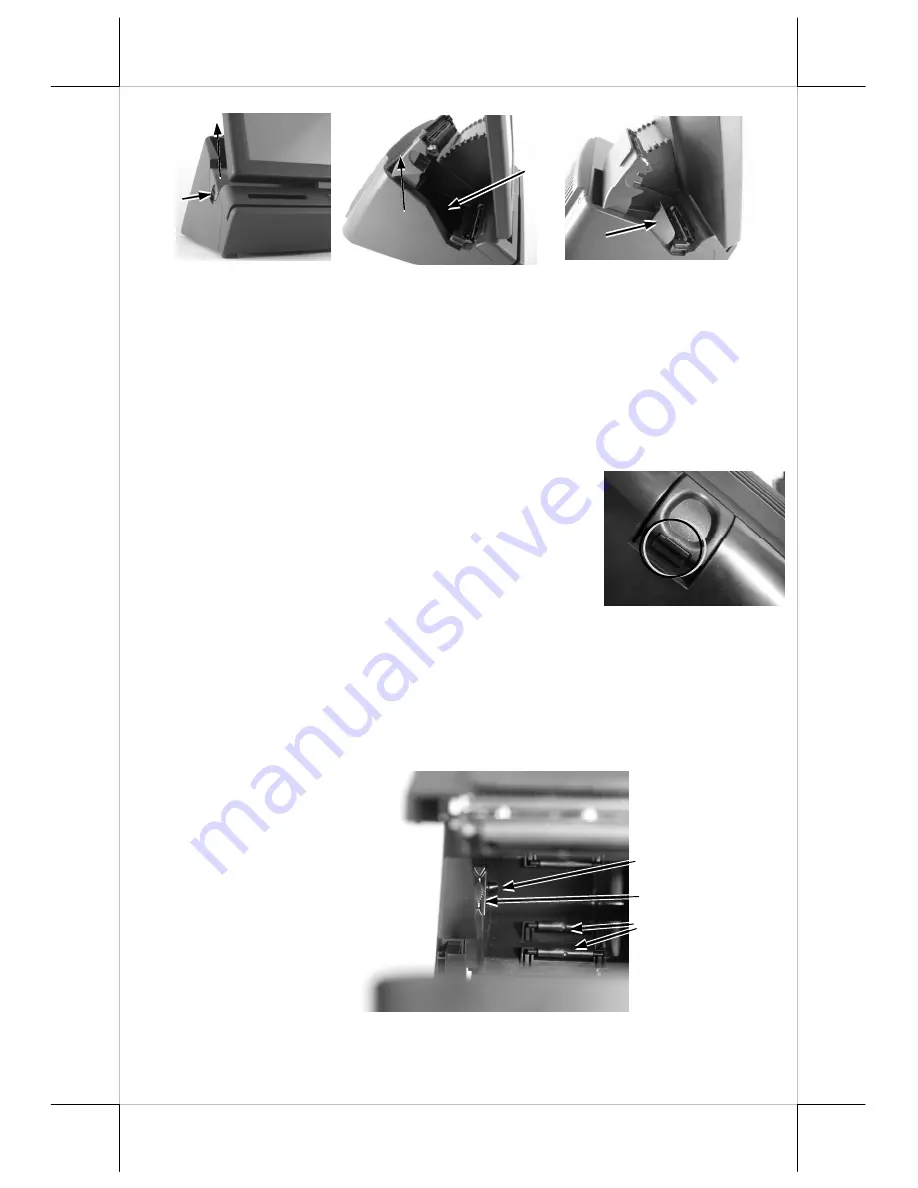
 Pull up the printer cover. 

Step D:

 Loading the paper roll and please notice that the paper roll’s 

orientation should be face the printer head.  

Step E:

 Please pull the paper longer then paper exit and close the printer cover 

at the centre of front and please watch your finger during this step in 
order to reduce hurt occur.  

After finished steps A to E, the printer will cut the excess paper automatically 
after the paper cover closed if the system power is turn on.  
 

Note 1:

 In order to protect the users’ fingers, 

please notice that the push lock button in the 
lock/release lever. When the LCD panel needs to be 
push or pull from the most rear end, please press 
the push lock and the lock/release lever at same 
time then the LCD panel can pull or pull from the 
rear end . Otherwise, the final level of tilt angel will be lock. The push lock 
button only work when push or pull the final level of the LCD panel 
adjustment. 


Paper Near End Sensor 

 
The  near  end  sensor  for 
paper  roll  in  the  printer 
is able to have the printer 
work  with  paper  rolls  of 
several 

bobbin 

sizes. 

Please 

refer 

to 

the 

picture  at  right  for  the 
inside  of  the  paper  roll 
compartment  that  there 
are  a  plastic  thumb 
wheel  for  bobbin  size 


Sensor Position  
Adjust 

Support Roller 

Sensor Block 

Summary of Contents for XP-3000 Series

Page 1: ...fits resulting from the furnishing performance or use of this material This information is provided as is and Posiflex Technology Inc expressly disclaims any warranties expressed implied or statutory...

Page 2: ...the busiest situation XP 3000 3300 Series applies Intel Pine View CPU technology fast speed Ethernet as well as plenty of connects ports of USB Serial VGA and CR ports It also integrated with thermal...

Page 3: ...Page 2 INTRODUCTION PRODUCT PICTURES Front Views Side Views Rear Bottom Views 1 2 3 4 5 6 7 8 9 10 11 14 15 16 17 9 12 13...

Page 4: ...Exit 14 Bottom plate compression lock 15 Bottom plate tenon 16 Rubber foot with bottom plate fixing screw 17 Bottom plate PRODUCT FEATURES Standard Features Models Item XP 3012H XP 3015H XP 3312H XP 3...

Page 5: ...imum Paper roller diameter 80mm Paper thickness Less then 86 m LCD panel tilt angle 14 55 degree Table Summary of features Models Item XP 3012E XP 3015E XP 3312E XP 3315E LCD Display TFT LCD Panel Dig...

Page 6: ...tems Note The underlined items in the following list means that option must be set prior to shipment from the factory The rest items can be set by the dealers a DDR2 SODIMM memory expansion up to 2GB...

Page 7: ...ple push on the switch in 10 sec may turn off the power Note There must always be at least 10 seconds waiting before switching on again once the system is powered off successfully Brightness Control I...

Page 8: ...video memory size is default in 128 MB and can be set to be 64 MB VGA Port The VGA port in the XP 3000 3300 system supports either a rear mount 2nd display or a separately connected LCD monitor or tou...

Page 9: ...mouse at the point when the touch panel is touched If the point touched is dragged across the screen surface it works as the mouse drag and drop feature If the point is touched released and touched wi...

Page 10: ...e that the push lock button in the lock release lever When the LCD panel needs to be push or pull from the most rear end please press the push lock and the lock release lever at same time then the LCD...

Page 11: ...in order to reduce the paper loss adjustable function please see following chapter Printer setup The printer will leave the advance paper in 4 8 mm long for each print It is highly suggested to print...

Page 12: ...ard s movement can be two way of the slot the reading process should be passing through whole slot horizontally A non standard card recorded without complete degaussing prior to recovery may accept on...

Page 13: ...e at right Next please unfasten these two screws which fasten the UPS bracket and take out the bracket as shown in the lower left picture Please take it out and place it in the battery compartment at...

Page 14: ...and pull up the terminal carefully than you will see the I O plate I O Plate View A 2x Serial Port RS 232 COM1 2 B 1x Serial Port RJ 45 COM3 C 1x LAN Port D 4x USB Ports E 1x CR Ports F 1x VGA Port D...

Page 15: ...connector be screwed into place once seated Please make sure that each connector has to be connected to the right device in the right way CAUTION On doing any insertion or extraction of any connector...

Page 16: ...t customer display kits for XP 3000 3300 series Counter space saving design with 2 20 VFD PD 2606 and 2 20 LCD PD 330 provides the clearest view for customers In addition real base mount graphic STN L...

Page 17: ...he CR port in XP system This cable has a 6 pole plug at one end and an 8 pole plug at the other The 8 pole plug should be inserted into the connector marked signal cable from POS Printer at the rear o...

Page 18: ...on This terminal must NOT be operated in an environment with restricted ventilation There must be at least 25 mm air clearance around any top or side ventilation holes with a free flow of air around t...

Page 19: ...iately A larger external battery may be connected to give an extended operation Please check your dealer about this capability when required WARNING If there are any signs of over charging or leakage...

Page 20: ...in system jumper setting and printer parameter setting However such support is limited to the application of specific Posiflex peripherals and must be disabled when the Posiflex peripherals are disco...

Reviews: