background image

PP2000 (E) User’s Manual

6 - 5

H. 

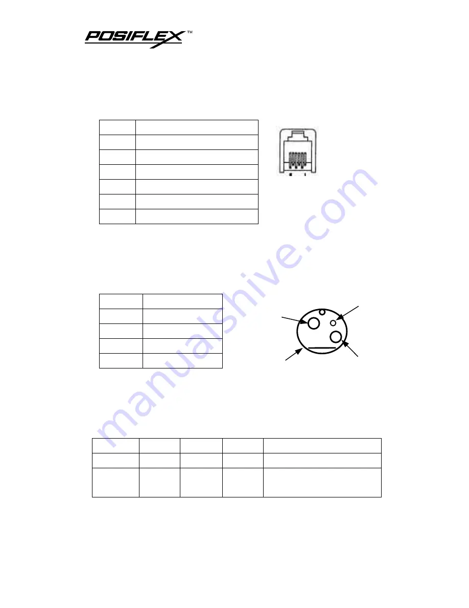
CASH DRAWER CONNECTOR

PIN

DEFINITION

1

Frame ground

2

CR2 kick (by Esc p 0 n1 n2)

3

Drawer open sense

4

+24V DC power

5

CR1 kick (by Esc p 1 n1 n2)

6

Signal ground

I. 

SERIAL INPUT CONNECTOR

(standard 9 pin RS232 interface)

J. 

POWER INPUT CONNECTOR

PIN

DEFINITION

1

+24 V DC power

2

Power ground

3

N. C.

CASE

Frame ground

K. 

PARALLEL INPUT CONNECTOR

(standard 25 pin SPP interface)

L. 

DIMENSION AND WEIGHT

Length

Width

Height

Weight

PRINTER 265 mm 176 mm

193 mm 2.5 Kg

PACKED 315 mm 240 mm

320 mm

3.8 Kg (w/o power adaptor)

4.5 Kg (w/ power adaptor)

1

3

CASE

2

Summary of Contents for PP2000 Series

Page 1: ...Rev A PP2000 Series 2 Station Printer User s Guide ...

Page 2: ...as of May 1989 Warranty Limits Warranty will terminate automatically when the machine is opened by any person other than the authorized technicians The user should consult his her dealer for the problem happened Warranty voids if the user does not follow the instructions in application of this merchandise The manufacturer is by no means responsible for any damage or hazard caused by improper appli...

Page 3: ...3 1 STORE STAMP INSTALLATION 3 2 RIBBON INSTALLATION REPLACEMENT 3 3 CASH DRAWER CONNECTION 3 4 CONNECT TO HOST COMPUTER 3 4 POWER CONNECTION 3 4 POWER ON 3 5 PAPER ROLLS INSTALLATION 3 5 SELF TEST 3 6 REPLACE TOP COVER 3 6 CLEAR BUFFER 3 6 MAINTENANCE NOTICES 4 1 SOFEWARE COMMANDS 5 1 SPECIFICATIONS 6 1 VALIDATION PRINTING 6 1 PAPER ROLL 6 1 LED INDICATIONS 6 2 BUTTON FUNCTIONS 6 2 PRINTER GENERA...

Page 4: ...ARALLEL INPUT CONNECTOR STANDARD 25 PIN SPP INTERFACE 6 5 DIMENSION AND WEIGHT 6 5 ENVIRONMENT 6 6 RELIABILITY 6 6 POWER ADAPTOR PA 300 6 6 REGULAR MAINTENANCE PROCEDURE 7 1 DAILY MAINTENANCE 7 1 PERIODIC MAINTENANCE 7 2 BASIC TROUBLES SHOOTING 8 1 NO OPERATION AFTER POWER ON 8 1 CAN NOT PRINT WITH A NORMAL POWER ON 8 1 USE SELF TEST CAPABILITY IN CASE OF DOUBT 8 1 PAPER JAMMED 8 2 ...

Page 5: ...onnector for serial interface and a 25 pin D subminiature connector for parallel interface and the printer can automatically detect which one is in use l High capacity of printing buffer max 32 KB can receive data speedily and store a large quantity of data l The ability of controlling two cash drawers l Built in stand by power to hold data for 1 hour from power off or power failure so that the pr...

Page 6: ...PP2000 E User s Manual 1 2 l Options include auto stamping ability of the store stamp on receipt and auto cutting of the receipt l The ability of cutting paper in full or in part by software on receipt ...

Page 7: ...N THE EXTERIOR A OUTPUT AREAS B CONTROL PANEL Receipt exit slot Journal window Validation printing insert slot Power LED On line LED Power On Off switch Receipt switch Journal switch Manual stamping switch Receipt LED Journal LED On line switch ...

Page 8: ...PP2000 E User s Manual 2 2 C INPUT OUTPUT CONNECTOR Cash drawer connector Serial connector Power connector Parallel connector ...

Page 9: ... sample l l One set of ribbon l l Power adaptor with power cord option If there is any discrepancy or problem contact your dealer immediately Be sure to save the packing materials in the event that the printer may need to be shipped at some point in the future B OPEN TOP COVER Please check the Power On Off switch to be Off Open top cover by gently pressing the rear part of top cover inward and lif...

Page 10: ...ndle with your fingers Disassemble the holder and the spring piece away from the stamp case then install the store stamp which is engraved with store name or logo and cushion and reassemble the spring piece and holder onto the stamp case as illustrated in the picture above Please note the direction Holder Spring piece Store stamp Cushion Store stamp case Assembled sample Top of stamp Print anvil a...

Page 11: ... When replacing the ribbon please take the handle at the center of the old ribbon case and lift it up Then the old ribbon can be taken out When installing a new ribbon please place the new ribbon to a suitable position and align the axle hole under the ribbon case to the driving axletree of the printer Then push down the ribbon case Now Location of the ribbon Handle of the ribbon Knob of the ribbo...

Page 12: ...onnector supports the RS232 series interface and the 25 pin D sub Male connector supports the parallel interface The protocol used in serial connection is defaulted 9 600 bps parity none 8 data bits 1 stop bit The baud rate is adjustable from 2 400 to 19 200 bps G POWER CONNECTION If used with Posiflex PST POS system PP2000 can use DC power and the power cable from the POS system If not user must ...

Page 13: ...he insert slot of receipt When the front end of receipt is shown from the front end of the insert slot release the receipt lever 3 Push and hold down the journal lever and insert the front end of journal into the insert slot of journal When the front end of journal is shown from the front end of the insert slot feed the paper enough to be fixed to the pick up reel of journal and release the journa...

Page 14: ...f there is any difficulty in applying all the five hooks on top cover into the bottom base of the printer always align the left three hooks first and then press down the top cover to the base In this way the top cover will not come in conflict with the receipt lever L CLEAR BUFFER The PP2000E series provides a data preservation function during power off This function helps the user to go on printi...

Page 15: ...g Please do not pour ink into the ribbon or it is easy to damage the print head Print head Replace for a new one every seventy thousand pieces of receipt journal printing Store stamp Add ink into store stamp once every three months or twenty thousand pieces of receipt journal printed To avoid illegible stamping please replace new store stamp once every twelve months or eighty thousand pieces of re...

Page 16: ......

Page 17: ...tion ESC 1B 25 Select cancel user defined characters set ESC 1B 26 Define user defined characters ESC 1B 2A Select bit image mode ESC 1B 2D Turn underline mode on off ESC 1B 3C Return home ESC 1B 3D Select peripheral device ESC 1B 3F Cancel user defined characters ESC 1B 40 Initialize printer ESC E 1B 45 Turn emphasized mode on off ESC G 1B 47 Turn double strike mode on off ESC R 1B 52 Select an i...

Page 18: ...p ESC p 1B 70 Generate pulse ESC t 1B 74 Select character code table ESC u 1B 75 Transmit peripheral device status ESC v 1B 76 Transmit paper sensor status ESC z 1B 7A Turn parallel printing mode on for receipt and journal GS 1D 2A Define download bit image GS 1D 2F Print download bit image ...

Page 19: ...aper thickness 0 07 0 14 mm Validation print One line Number of characters 55 Print area and sensor position As illustrated in drawing above B PAPER ROLL Paper type High quality paper Paper roll width 44 5 0 5 mm Paper roll max O D 83 mm Paper thickness 0 06 0 09 mm Print area 2 8 10 84 5 22 Unit mm Note Do not scale Sensor ...

Page 20: ...malfunction with journal print D BUTTON FUNCTIONS On line button Switches the printer between on line and off line states The data in the buffer keep printing out Receipt button Feeds receipt forward one line by each press under off line state Journal button Feeds journal forward one line by each press under off line state Can be used to clear buffer if the printer switched on while both this butt...

Page 21: ...al by separate friction feed Max Paper Feed Speed About 30 lines sec Built in Characters 3 code pages with 16 international character sets Data Buffer 32KB max Paper Type Receipt paper roll 44 5 mm wide x 83 mm max O D Journal paper roll 44 5 mm wide x 83 mm max O D Validation single sheet or 2 layers of auto copy Inked Ribbon EPSON ERC 32 P purple Receipt Auto Cut Pattern Full cut 1 point left un...

Page 22: ...material of stamp G INTERNAL SWITCHES Dismount the 4 screws at bottom of the printer and there is a control board fixed on a steel plate On this control board there is a 4PST DIP switch The functions of each position of this DIP switch are described below P1 For factory setting should not be changed P2 For data preservation ON data in input buffer remains when power off OFF data in input buffer ar...

Page 23: ...ound I SERIAL INPUT CONNECTOR standard 9 pin RS232 interface J POWER INPUT CONNECTOR PIN DEFINITION 1 24 V DC power 2 Power ground 3 N C CASE Frame ground K PARALLEL INPUT CONNECTOR standard 25 pin SPP interface L DIMENSION AND WEIGHT Length Width Height Weight PRINTER 265 mm 176 mm 193 mm 2 5 Kg PACKED 315 mm 240 mm 320 mm 3 8 Kg w o power adaptor 4 5 Kg w power adaptor 1 3 CASE 2 ...

Page 24: ... average O POWER ADAPTOR PA 300 ITEM SPECIFICATION INPUT VOLTAGE RANGE 100 V AC to 250 V AC INPUT FREQUENCY 50 to 60 Hz OUTPUT VOLTAGE 24 V DC OUTPUT POWER max 60 W CONTINUOUS LOAD max 2 2 A OUTPUT STABILITY 5 RIPPLE AND NOISE max 240 mV Any application of a non Mustek supplied standard power adaptor may cause damage to the printer abnormal operation or noise interference All such degradations are...

Page 25: ...Use the attached soft brush to clean the insert slot area in the direction as indicated in Fig 2 Brush gently away the dust and paper residuals in the direction from the journal end to the receipt end 4 Check for dust and paper residuals in the stamp area Use the attached soft brush to clean this area as indicated in Fig 3 5 Replace the print anvil assembly Use mini vacuum cleaner if necessary to ...

Page 26: ...PP2000 E User s Manual 7 2 B PERIODIC MAINTENANCE A periodic maintenance and lubrication should take place by a qualified maintenance specialist in every 6 months ...

Page 27: ...the power LED does lit please contact the service dept of the manufacturer B CAN NOT PRINT WITH A NORMAL POWER ON 1 Check if the on line LED is turned on 2 Check if the interface cable is securely connected Go on operation after fixing every joint 3 Check if the interface cable is incorrectly connected C USE SELF TEST CAPABILITY IN CASE OF DOUBT Power off the printer first Press and hold the recei...

Page 28: ...erious paper jammed problem please pull both the receipt lever and the journal lever forward and push the print anvil assembly backward as indicated in the picture to raise the print anvil assembly Receipt lever Journal lever Raise the print anvil assembly ...

Page 29: ...the area before putting back the print anvil assembly if the condition requires When you are putting back the print anvil please pay special attention to the position of the pick up reel for journal Because the journal pick up reel moves backward automatically when the print anvil is raised Pick up reel moves back Original location ...

Page 30: ...oes not automatically move forward when the print anvil assembly is put back Please then put the journal pick up reel back to its original location and roll the reel so that the journal remains properly tensioned Direction to roll No auto return with print anvil ...

Reviews: