background image


Part 1 


FCC Notes: 

This equipment generates, uses, and can radiate radio frequency energy 
and, if not installed and used in accordance with the instructions manual, may cause interference to 
radio  communications.  It  has  been  tested  and  found  to  comply  with  limits  for  a  Class  A  digital 
device  pursuant  to  subpart  J  of  Part 15  of  FCC Rules,  which  are  designed  to provide  reasonable 
protection  against  interference  when  operated  in  a  commercial  environment.  Operation  of  this 
equipment  in  a  residential  area  is  likely  to  cause  interference  in  which  case  the  user  at  his  own 
expense will be required to take whatever measures to correct the interference. 

CE manufacturer’s Declaration of Conformity 
(EC Council Directive 89/336/EEC of 3 May 1989) 

This product has been designed and manufactured in accordance with the International Standards 
EN50081-1/01.92  and  EN50082-1/01.92  following  the  provisions  of  the  Electro  Magnetic 
Compatibility Directive of the European Communities as of May 1989 

Warranty Limits: 

Warranty  terminates  automatically  when  any  person  other  than  the  authorized  technicians  opens 
the machine. The user should consult his/her dealer for the problem happened. Warranty voids if 
the user does not follow the instructions in application of this merchandise. The manufacturer is by 
no means responsible for any damage or hazard caused by improper application. 

About This Manual: 

Posiflex has made every  effort for the accuracy of the content in this manual. However, Posiflex 
will  assume  no  liability  for  any


technical  inaccuracies  or  editorial  or  other  errors  or  omissions 

contained herein, nor for direct, indirect, incidental, consequential or otherwise damages, including 
without limitation loss of data or profits, resulting from the furnishing, performance, or use of this 
material.


This  information  is  provided  “as  is”  and  Posiflex  Technology,  Inc.  expressly  disclaims  any 
warranties,  expressed,  implied  or  statutory,  including  without  limitation  implied  warranties  of 
merchantability or fitness for particular purpose, good title and against infringement. 
The information in this manual contains only essential hardware concerns for general user and is 
subject  to  change  without  notice.  Posiflex  reserves  the  right  to  alter  product  designs,  layouts  or 
drivers  without  notification.  The  system  integrator  shall  provide  applicative  notices  and 
arrangement  for  special  options  utilizing  this  product.  The  user  may  find  the  most  up  to  date 
information of the hardware from web sites: http://www.posiflex.com or  
http://www.posiflex.com.tw or http://www.posiflexusa.com 
All  data  should  be  backed-up  prior  to  the  installation  of  any  drive  unit  or  storage  peripheral. 
Posiflex will not be responsible for any loss of data resulting from the use, disuse or misuse of this 
or any other Posiflex product. 
All  rights  are  strictly  reserved.  No  part  of  this  documentation  may  be  reproduced,  stored  in  a 
retrieval system, or transmitted in any form or by any means, electronic, mechanical, photocopying, 
or otherwise, without prior express written consent from Posiflex Technology, Inc. the publisher of 
this documentation. 

©

 Copyright Posiflex Technology, Inc. 2012


All brand and product names and trademarks are the property of their respective holders.


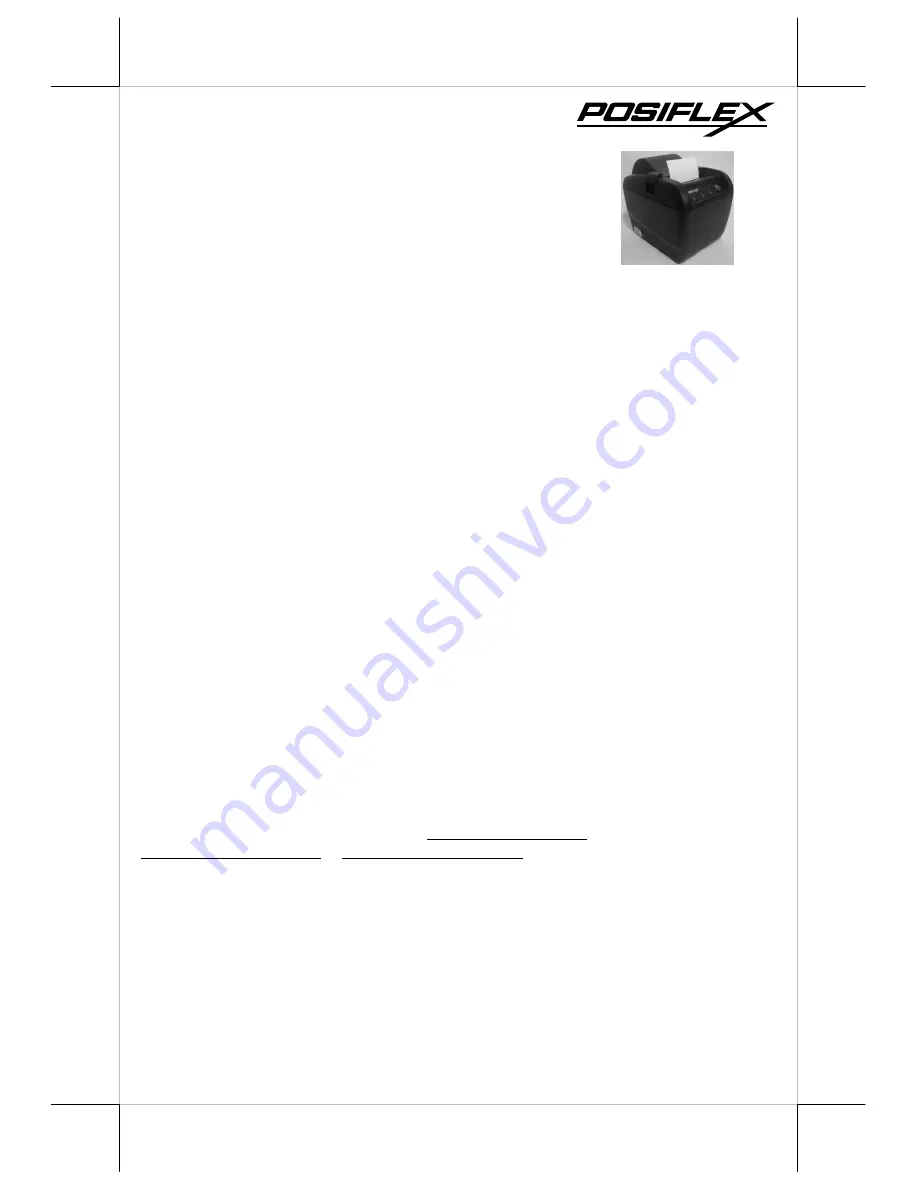
PP-6900 Series 

 THERMAL PRINTER 

USER’S MANUAL 

Rev.: Original 

P/N: 19780901010 

Summary of Contents for PP-6900 Series

Page 1: ...torial or other errors or omissions contained herein nor for direct indirect incidental consequential or otherwise damages including without limitation loss of data or profits resulting from the furnishing performance or use of this material This information is provided as is and Posiflex Technology Inc expressly disclaims any warranties expressed implied or statutory including without limitation ...

Page 2: ...ber also with USB ports supported The standard model of PP 6900 is USB interface PP 6900S is Serial interface PP 6900W is Wi Fi interface and for PP 6900P is parallel interface The PP 6900L connects to a LAN port of POS systems The PP 6900 is able to connect the USB port of POS systems either true USB interface application or simulates a RS232 device through driver and performs thermal printing pa...

Page 3: ...5 pin D sub Female connectors for PP 6900P parallel model d No interface cable for PP 6900L or PP 6900W Length of the interface cable depends on whether the order includes the power adaptor When power adaptor is included the interface cable is 6 ft long for stand alone application When the power adaptor is not included in the order the interface cable is a shorter one for integrated application in...

Page 4: ...CTURES Top View Front View Bottom View Bottom Cover Power Switch Power LED Error LED Paper Out LED FEED Switch Top Cover Hood Release Paper Exit Rubber Foot Window Plate Screw Setup Window Plate Rubber Foot Paper Cover ...

Page 5: ...USB Port Serial Port Serial Adaptor Fixation Screw I O Area for PP 6900S Parallel Port Parallel Adaptor Fixation Screw I O Area for PP 6900P Wi Fi Indicator Reset Button I O Area for PP 6900W LAN Port LAN Adaptor Fixation Screw I O Area for PP 6900L Reset Button Wi Fi Adaptor Fixation Screw ...

Page 6: ...hood and the top cover as in Pix 3 5 Excessive paper will cut or roll automatically when changing the paper at power on status When to Replace Paper Whenever the printer gives paper out signal or a red line appears on the thermal paper it is the proper timing for replacing the paper Do not wait till the print engine is dragging the paper roll at the very end Remove the leftover and replace a new p...

Page 7: ...A virtual serial port is a redirector driver used in USB interface which is usually used to create a pair of back to back virtual COM ports on the same computer It can then communicate using virtual serial ports instead of conventional inter process communication mechanisms Parallel Connection The parallel connector is a 25 PIN D sub Male connector Apply the female end of the parallel cable at thi...

Page 8: ... 3 PIN jack Either a Posiflex supplied power adaptor or a printer power cable from a Posiflex POS system can be connected to this connector to supply power for this printer During insertion of the power plug be sure to hear the click to obtain a firm contact CAUTION Before doing the insertion or extraction of the power plug be sure to pull the outer sleeve of the plug backward to release the inter...

Page 9: ...compartment when paper near end The acceptable paper roll bobbin outer diameter is between 18 and 24 mm 58mm Paper Spacing Plate The application of 58 mm width paper roll in this printer can be achieved through adoption of an option spacing plate and an internal DIP switch setting Please refer to the last chapter of this manual for the DIP switch setting Please refer to the middle picture above fo...

Page 10: ...seconds into this hole will reset the LAN Wi Fi setup of the printer back to the default values at delivery so the user may re do all setup The LAN setup can be viewed in the second paragraph of self test printout for the PP 6900L LAN POS Printer Manager This utility can be used to manage multiple PP 6900L s connection in the same network under Windows as long as there is no conflicting IP in the ...

Page 11: ...PP 6900W right after change or update setting OPERATION GUIDE MAINTENANCE GUIDE LINES Always turn off and disconnect power before opening the cover The areas around the print head and motor become very hot during and just after printing DO NOT touch them When handling the interior of the thermal printer please pay attention not to be hurt by any sharp edge of the metal parts GENERAL CLEANING Pleas...

Page 12: ...side the printer to assure the locking of the hood for a decent printing Therefore any dislocation of the hood may cause an error status and inhibition to printing Press down the hood at in the middle of the opening when closing it till it audibly clicks into place If both situations are not the cause please try pulling the hood lock forward If the top hood won t release automatically check for pa...

Page 13: ...seful in finding software problems To start the dump mode Turn off printer Open print hood Hold down FEED button while turning printer on Close the hood To stop the dump mode Press the FEED button to print out the last line Turn off the printer During dump mode All commands except DLE EOT and DLE ENQ are disabled USEFUL TIPS Please note that only those qualified technicians may adjust several jump...

Page 14: ... after copying the printed surface may be discolored Use only water paste starch paste polyvinyl paste or CMC paste when gluing thermal paper If thermal paper touches anything containing phthalic acid ester plasticizer for a long time the image formation ability may be reduced or the printed image may fade Use of volatile organic solvents such as alcohol ester and ketone or some adhesive tapes on ...

Page 15: ...aper thickness 60 80 um POWER ADAPTOR ITEM REQUIREMENT Input voltage 100 V AC 240 V AC Input frequency 50 60 HZ Input current 1 8 A MAX 115 V AC Output voltage 24 V DC Output power 50 W Static load 0 A 2 08A Output regulation 5 EMI standards VDE A FCC A VCCI A MULTIPLE INTERFACE ISSUE For model PP 6900 there is only 1 connector for host connection through USB For PP 6900P there are 2 connectors fo...

Page 16: ... switches settings DIP Switch On bottom cover of the PP 6900 series thermal printer there is a screwed metal plate for setup window In this window there is an 8 position DIP switch for printer setup Please use proper tool to change the switch setting when necessary The switch position counting starts from the nearest edge of printer The functions of each position may evolve with the revisions of t...

Page 17: ...up for PP 6900 OFF ON OFF OFF OFF OFF OFF OFF Software switch Another method to set up PP 6900 series is through the software switch setting which means that other functions must be changed by software utility Please visit our web site http www posiflex com or http www posiflex com tw to download the PP 6900 software switch utility Software switches has divided into SW1 SW2 SW3 and SW4 The followi...

Page 18: ... care of enough paper feed for printed lines cut prevention issue For switch position 2 5 if the switch is set to ON the busy signal set to host only when input buffer is full When it is set to OFF busy signal is sent to host whenever the input buffer is full or an off line status occurs Therefore signals including the paper near end detect will generate busy signal to the host Moreover the printe...

Page 19: ...ies 3 Pass when it is set to On it signifies 1 Pass when it is set to Off For switch position 3 4 UPOS Auto Write is enabled when it is set to On Off it is disabled For switch 3 5 6 7 8 Print Density Adjust is enabled Effect of positions 5 6 7 8 on Print Density is defined as below SW3 Pos 5 OFF ON OFF ON OFF ON OFF ON OFF ON OFF SW3 Pos 6 OFF OFF ON ON OFF OFF ON ON OFF OFF ON SW3 Pos 7 OFF OFF O...

Page 20: ...ON ON Line Space Reduce Disable Reduce 25 Reduce 50 Reduce 75 For switch 4 position 6 7 it can reduce the spare space between paragraphs No matter how many blank lines this function will reduce the total unused space for three particular percentages which are 25 50 and 75 Please refer to the following table to adjust switch 4 6 7 Effect of positions 6 7 on Line Feed Reduction as in table below SW4...

Reviews: