background image

Page 7


Do not overdo the tightening or unrecoverable thread damage will occur.


PD-309UE for KS or DT series


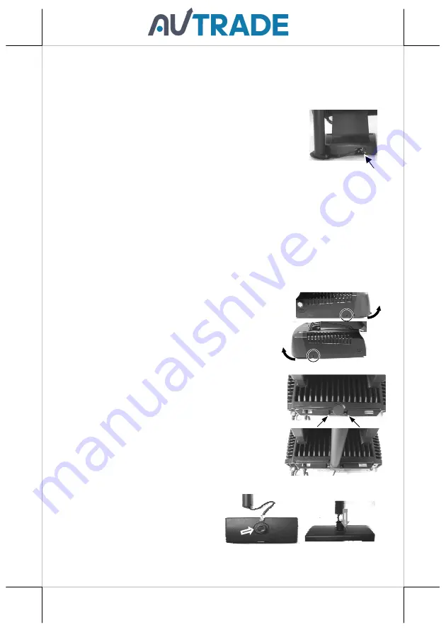
The PD-309UE can be attached to the corner in bottom plate of the KS series, 
with  slim  base,  DT  series  and  Gen.6  &  5  base  of  KS 
series. It takes examples of this LCD customer display to 
fix in the KS series, and DT series. Refer to the pictures 
in 

Pix.1

  at  right.  Use  the  3  attached  screws  to  fix  the 

metal base plate of the PD to bottom of mini slim base or 
DT-20X  at  the  circled  positions.  For  mini  slim  base, 
connect  the  interface  cable  to  go  into  the  base  through  cable  exit  arrowed  in 

Pix.2

  at  right  to  the  main  unit.  For  DT-20X  arrange  the  interface  cable  to  go 

through under bottom to connector area arrowed in 

Pix.1

 at above right.  

CAUTION:  There  are  self-tapping  screws  for  PD-309UE  when  available 
in  Gen.  5  base  stand  and  please  aim  to  the  holes  which  marked  “DT”  as 
shown  in  the  upper  picture  Pix.1.  Other  Bing  Head  Screws  are  available 
when fixed in KS series, DT series and Gen.6 base stand of KS series. 

PD-308UE for FT series: 

1.

To install PD-308UE onto FT series host system,
the  back  cover  of  FT  system  base  has  to  be
opened.  First  push  in  the  circled  knobs  on
both  sides  as  in  the  right  pictures  to  remove
the back cover.

2.

Remove  the  pole  cover  on  rear  edge  of  the
base top cover of FT system by first removing
the  2  arrowed  screws  in  the  left  picture  and
then pushing the wedge shaped pole cover up.

3.

Insert  the  base  of  PD-308UE  from  top  of  FT
system base and screw back the 2 screws as in
the  right  picture.  Connect  the  interface  cable
to appropriate port.

Stand Alone Model: 

This instruction is for stand alone 
model only. Please unpack the inner 
box of pole display and it is easy to 
find the base, display unit with tube 
and adaptor separately. Please 
remove the PE foam and bring out the components carefully. 

Pix. 2 

Summary of Contents for PD-30 UE Series

Page 1: ...shing performance or use of this material This information is provided as is and Posiflex Technologies Inc expressly disclaims any warranties expressed implied or statutory including without limitation implied warranties of merchantability or fitness for particular purpose good title and against infringement The information in this manual contains only essential hardware concerns for general user ...

Page 2: ...table command emulation modes including PST and EPSON command emulation modes 3 typical USB interface modes USB HID Class USB Vendor Class Virtual COM port selectable by DIP switch Euro and Rupee dollar signs supported INSTALLATION GUIDES HOST SYSTEM PREPARATION Except for PD 320UE 303UE 300UE which is a stand alone pole display only PD 300UE is required with an external power adaptor and needs to...

Page 3: ...over of XT main unit and fasten them to fix PD on the XT series PD 340UE for HS series A Hold the PD unit item then turn the screen facing toward you B Please find the 4 holes on the rear panel of HS series system C Please aim the 4 PD bracket holes to the 4 screw holes on the back cover of HS main unit and fasten them to fix PD on the HS series PD 330UE for XP series A Please take the bracket and...

Page 4: ...stomer pole display it can operate straight away and no needs to assemble with any other host system Nevertheless it also can fix on the counter or any place when it needs to be fixed The following pictures A to D will describe such as how to adjust the height of the pole and how to fasten the PD 320UE in a flat surface ...

Page 5: ...profile of display s height After adjusting to a satisfactory height please push back the compress lock to fix the tube Note Please align the compress lock and the grooves in order to fix the height of customer display Picture B is going to show how to screw PD 320UE in a flat surface In the base stand of PD 320UE there are two screw holes for user to fix the customer display Please choose a flat ...

Page 6: ...iangle marked in the upper right picture However please do not screw them to the bottom but at a position that is about 1 turn loose from the bottom Similarly please loosen the screws by 1 turn for some KS models with these 2 screws preinstalled For PD 310AUE fixed to KS series please kindly follow steps below A Find the lower 2 holes as indicated on the main unit B Aim the 2 screws into the 2 hol...

Page 7: ...5 base stand and please aim to the holes which marked DT as shown in the upper picture Pix 1 Other Bing Head Screws are available when fixed in KS series DT series and Gen 6 base stand of KS series PD 308UE for FT series 1 To install PD 308UE onto FT series host system the back cover of FT system base has to be opened First push in the circled knobs on both sides as in the right pictures to remove...

Page 8: ...y and route the cable as arrowed in the right picture PD 307UE for HT series 1 For ease of PD 307UE installation operation the HT main unit or PB system has to be opened with sufficient precautions First push in the circled knobs on both sides as in the right picture to remove the back cover Take out the arrow pointed pole cover from it 2 Prepare a piece of clean soft clothe of appropriate size in...

Page 9: ...tures the cable is eliminated for the sake of minimum visual confusion 5 Turn the pole display base unit opposite to have the bottom locking lugs A facing left and now insert the 2 bottom locking lugs A on base unit into the 2 rectangular installation holes A on bottom of HT or PB chassis from the right corner with the pole display slightly inclined to the left as in the upper picture at right Ple...

Page 10: ... turn the upper end of pole display to the left to remove the locking lugs A from bottom chassis A Ignorance of this point may damage or even break off the locking lugs A due to improper torque applied 8 The screw bosses on base of PD 307UE should now align with the screw holes on sidewall of system chassis Only 1 screw needs to be applied Use the self tapping screw that comes with PD 307UE to fix...

Page 11: ...TP series main unit as circled in the right picture Then aim both metal and plastic hooks at rear of the PD302UE series toward the suitable ventilation openings on top rear of the main unit Please use a Phillips head sign screw driver to fasten the screws on the metal hook but not to overdo it so that the metal hooks hold the ribs of the ventilation holes from inside 2 Plug the other USB end of PD...

Page 12: ...in the picture below There is a small piece of plastic cover for the DIP switch window Slide the cover downward but don t pull it off otherwise you may have to practice for inserting it back You can find 4 positions of DIP switches in this window Adjust for the appropriate interface used by the DIP switch according to below table Switch position counts from left to right and ON means pushed up as ...

Page 13: ...flex Product Information CD or download it from web site http www posiflex com english 03_support 03_download php prod ajc ca te ajY and execute the file SETUP EXE to install the OPOS Control Manager To add the customer display under OPOS control please set in OPOS Control Manager device name PD3x Line Display in the top row SPECIFICATION OPTICAL Number of digits 20 digits row 2 rows Dot matrix 5 ...

Page 14: ...g WARNING If the user opens the pole display housing to make any modification all the product warranty will be voided NOTE Please refer to Posiflex Product Information CD or visit our web http www posiflex com tw for further information when needed APPENDIX APPLICABLE COMMANDS EPSON COMMAND MODE POWER ON DEFAULT NAME HEX CODES FUNCTION BS 08 Move Cursor Left HT 09 Move Cursor Right LF 0A Move Curs...

Page 15: ...3 n Cursor On Off n 1 0 US E 1F 45 n Blink Display Screen n 0 255 PST COMMAND MODE HEX CODES FUNCTION 06 N1 N2 Change Leading Code 14 01 Wraparound Mode Default 14 02 Vertical Scroll Mode 14 03 Insert Mode 14 04 Overwrite Mode Default 14 08 Back Space 14 09 Move Cursor Right 14 0A Move Cursor Down 14 0B Move Cursor Left 14 0C Delete Character 14 0D Move Cursor To Left Most Position 14 0E Clear Dis...

Page 16: ... Of Line 1 14 1C Move Cursor To Rightmost Position Of Line 2 After selecting code page table 19 the Euro Dollar Sign is designated at code D5 h After selecting code page table 96 the Rupee Dollar Sign is designated at code 60 h 警告使用者 警告使用者 警告使用者 警告使用者 這是甲類的資訊產品 在居住的環 境中使用時 可能會造成射頻干 擾 在這種情況下 使用者會被要 求採取某些適當的對策 ...

Reviews: