background image


Part 1 


FCC Notes: 

This  equipment  generates,  uses,  and  can  radiate  radio 
frequency energy and, if not installed and used in accordance 
with the instructions manual, may  cause interference to radio 
communications. It has been tested and found to comply with 
limits for a Class A digital device pursuant to subpart J of Part 
15  of  FCC  Rules,  which  are  designed  to  provide  reasonable  protection  against 
interference when operated in a commercial environment. Operation of this equipment 
in  a  residential  area  is  likely  to  cause  interference  in  which  case  the  user  at  his  own 
expense will be required to take whatever measures to correct the interference. 

Warranty Limits: 

Warranty  terminates  automatically  when  any  person  other  than  the  authorized 
technicians opens the machine. The user should consult his/her dealer for the problem 
happened. Warranty voids if the user does not follow the instructions in application of 
this  merchandise.  The  manufacturer  is  by  no  means  responsible  for  any  damage  or 
hazard caused by improper application. 

About This Manual: 

Posiflex has made every effort for the accuracy of the content in this manual. However, 
Posiflex  will  assume  no  liability  for  any


technical  inaccuracies  or  editorial  or  other 

errors  or  omissions  contained herein,  nor  for  direct,  indirect,  incidental,  consequential 
or  otherwise  damages,  including  without  limitation  loss  of  data  or  profits,  resulting 
from the furnishing, performance, or use of this material.


This information is provided “as is” and Posiflex Technology, Inc. expressly disclaims 
any  warranties,  expressed,  implied  or  statutory,  including  without  limitation  implied 
warranties  of  merchantability  or  fitness  for  particular  purpose,  good  title  and  against 
infringement. 
The  information  in  this  manual  contains  only  essential  hardware  concerns  for  general 
user and is subject to change without notice. Posiflex reserves the right to alter product 
designs,  layouts  or  drivers  without  notification.  The  system  integrator  shall  provide 
applicative notices and arrangement for special options utilizing this product. The user 
may  find  the  most  up  to  date  information  of  the  hardware  from  web  sites: 
http://www.posiflex.com or http://www.posiflex.com.tw 
All  data  should  be  backed-up  prior  to  the  installation  of  any  drive  unit  or  storage 
peripheral. Posiflex will not be responsible for any loss of data resulting from the use, 
disuse or misuse of this or any other Posiflex product. 
All  rights  are  strictly  reserved.  No  part  of  this  documentation  may  be  reproduced, 
stored  in  a  retrieval  system,  or  transmitted  in  any  form  or  by  any  means,  electronic, 
mechanical,  photocopying,  or  otherwise,  without  prior  express  written  consent  from 
Posiflex Inc. the publisher of this documentation. 

© Copyright Posiflex Technology, Inc. 2011


All brand and product names and trademarks are the property of their respective holders. 

PD – 2600 / 2601 / 2602 / 2603 Series 

User’s Manual 

                                                     Rev. D0 

P/N: 19460901150 

Summary of Contents for PD - 2600

Page 1: ...tation loss of data or profits resulting from the furnishing performance or use of this material This information is provided as is and Posiflex Technology Inc expressly disclaims any warranties expressed implied or statutory including without limitation implied warranties of merchantability or fitness for particular purpose good title and against infringement The information in this manual contai...

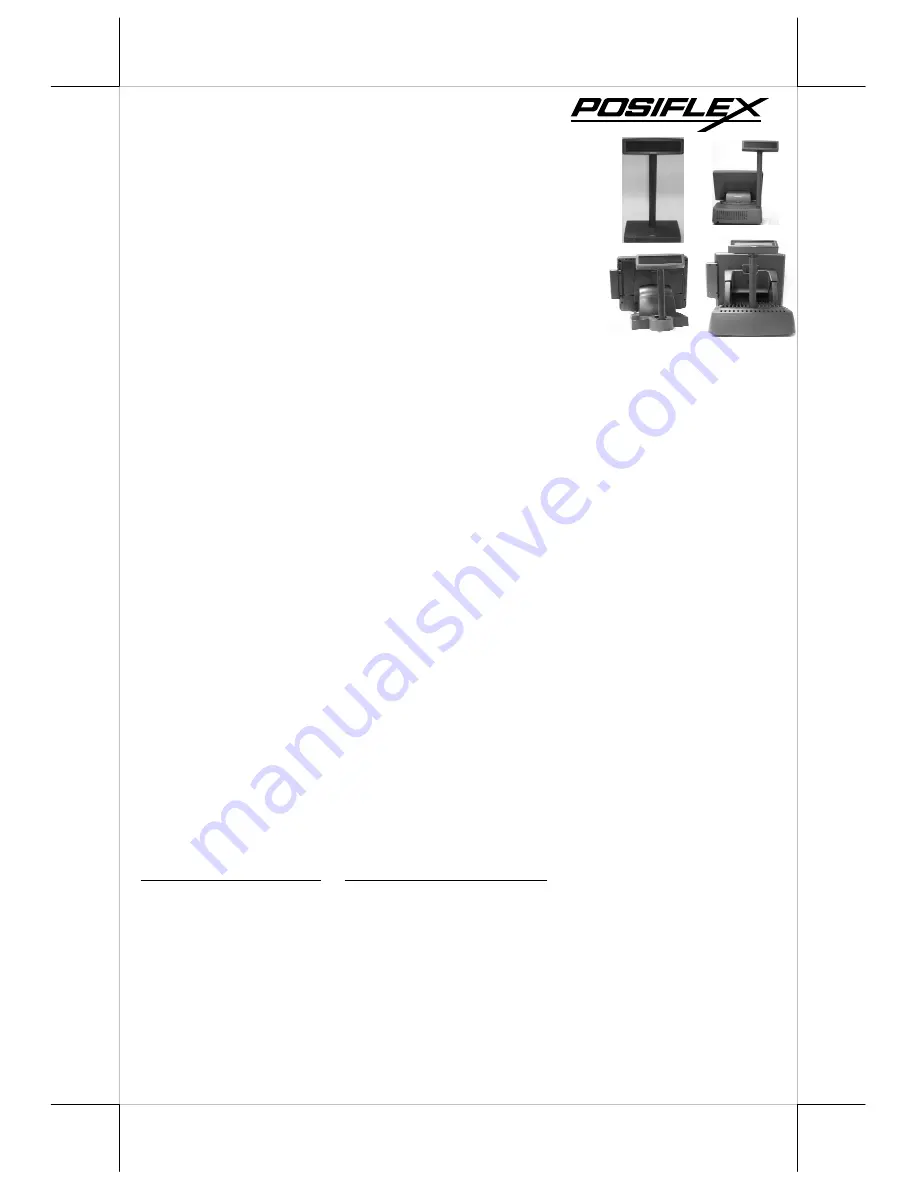
Page 2: ...id terminals or PB series discrete systems or KS or FT series fan free touch POS terminals or TP series touch POS terminals Two line display with 20 characters per line Adequately large characters for easy viewing 9 03 mm by 5 25 mm Long life and trouble free operation 15 30 and 45 adjustable viewing angles Total height 410 mm Stand alone Total height 392 mm PD 2601 on base of HT and PB series Tot...

Page 3: ...rwise there could be the power shortage problem INSTALLING PD 2600 In base of stand alone models PD 2600 models only looking from rear side of the bottom the connector area will look like below For serial RS232 interface models The RJ45 type modular connector is for internal use and is already occupied The RS232 input port is a DB9 female connector Connect the attached RS 232 signal cable to this ...

Page 4: ...ease remove the PE foam and bring out the components carefully Firstly place the display head and tube on a flat surface and find the cable which in the end of tube Let this cable pass through the short tube which on the base stand and it shows in the picture at right Next please assemble the display head with tube to the base stand which shows in the right picture Please pay more attention during...

Page 5: ... straight up position For both HT and PB system push in the rectangular marked spring button in Pix 1 on both sides of chassis and raise the rear edge of the top cover The COM port DC support can be set at this moment Find joining points on system Refer to Pix 2 that is a picture of the HT or PB chassis near the right bottom corner as you are facing the HT or PB system from its back with several p...

Page 6: ... in Pix 3 facing left and now insert the 2 bottom locking lugs A on base unit into the 2 rectangular installation holes A on bottom of HT or PB chassis from the right corner with the pole display slightly inclined to the left as in Pix 4 Please note that both bottom locking lugs A should be completely inserted and come out of the bottom plate of HT or PB system as emphasized by an arrow in the enl...

Page 7: ...m chassis Only 1 screw needs to be applied Use the self tapping screw that comes with PD 2601 to fix from external side of sidewall as demonstrated in Pix 6 Connect interface cable Carefully close back the top cover of HT or PB system and connect the interface cable of PD 2601 to appropriate port in system connector area Then close the back cover of the system INSTALLING PD 2602 Opening the rear c...

Page 8: ...oint tight INSTALLING PD 2603 Open back cover on system First push in the circled knobs on both sides as in Pix 11 to remove the back cover Remove pole cover Remove the pole cover on rear edge of the base top cover of FT system by first removing the 2 arrowed screws in Pix 12 and then pushing the wedge shaped pole cover up Install PD and connect interface cable Insert the base of PD 2603 PD 2603U ...

Page 9: ...sed for the application program POWER ON SIGN With interface cable connection well installed and with COM port power set for serial models turn on the HT or KS or TP Posiflex POS system a firmware identifier as power on sign will appear on the pole display screen for a while to indicate that pole display is self tested O K and ready to work USING THE CUSTOMER DISPLAY INTERRFACE SELECTION This seri...

Page 10: ...NO NO YES PT DRIVER INSTALLATION For application software to use RS232 interfaced PD 260X there is no direct need for any driver The OPOS OLE POS driver or the JPOS Java POS driver would be required for OPOS or JPOS programs and the PD 260X would have to be set to Epson command mode These drivers are available from our web page http www posiflex com tw Download 20list asp Status 1 Series_Name U PO...

Page 11: ...d Depth 39 5 mm Case color Black or Ivory ELECTRICAL Power from interface port of FT HT KS TP system 5VDC 1A ENVIRONMENTAL Operating temperature 0 to 40 C Storage temperature 20 to 70 C Operating humidity 20 to 85 non condensing Storage humidity 5 to 90 non condensing WARNING If the user opens the pole display housing to make any modification all the product warranty will be voided NOTE Please ref...

Reviews: