background image


2


II.  CARTON CONTENTS 

1.  LCD or Touch Monitor (Main unit + Adjustable stand assembly) 
2.  User’s Manual 
3.  Plastic key for cable cover latch 
4.  VGA cable: 20863136610 
5.  RS232 cable:  20863244210 (for TN4115 only) 
6.  Posiflex Product Information CDROM (for TM4115 only) 
7.  Power adaptor: 12 V DC ASP0P042WTB001 & power cord 

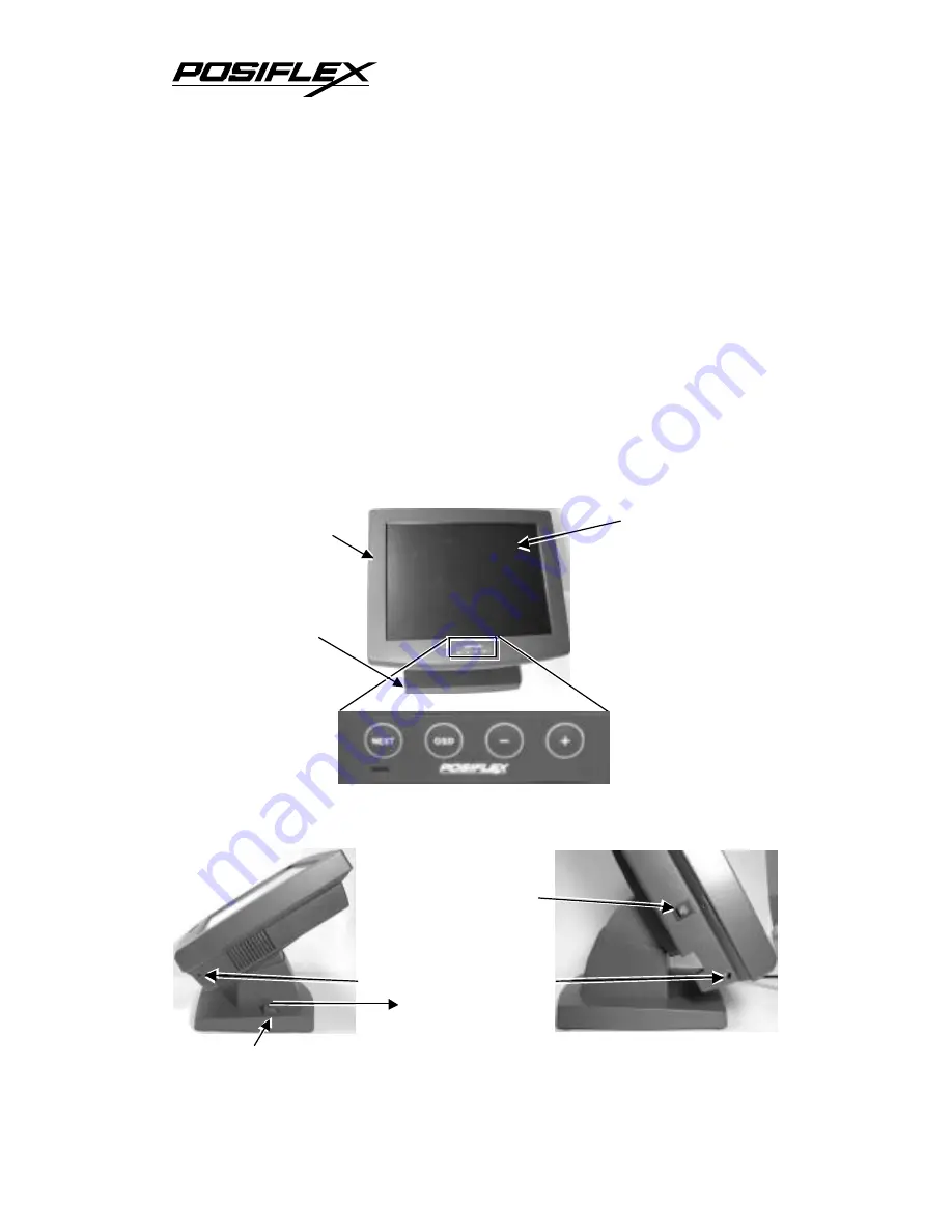
III.  PARTS IDENTIFICATION 

A.  FRONT VIEW 


B.  SIDE VIEWS 


Lock/release lever 

Push in this direction 
to adjust the tilt angle 
of the display panel 

Latch hole for cable cover 

Power on/off switch 
(Press on white dot 
to turn power on) 

Display Screen 
+ Touch Panel 

Main Unit 

Adjustable 
Stand Assembly 

Summary of Contents for LM4115

Page 1: ...n a residential area is likely to cause interference in which case the user at his own expense will be required to take whatever measures to correct the interference WARRANTY LIMITS Warranty will terminate automatically when the machine is opened by any person other than the authorized technicians The user should consult his her dealer for the problem happened Warranty voids if the user does not f...

Page 2: ... only 6 Posiflex Product Information CDROM for TM4115 only 7 Power adaptor 12 V DC ASP0P042WTB001 power cord III PARTS IDENTIFICATION A FRONT VIEW B SIDE VIEWS Lock release lever Push in this direction to adjust the tilt angle of the display panel Latch hole for cable cover Power on off switch Press on white dot to turn power on Display Screen Touch Panel Main Unit Adjustable Stand Assembly ...

Page 3: ...e cover 2 Press down the lock release button on back of stand assembly when lifting the main unit to separate it from the stand Route all cables through the cable exit in bottom of stand assembly Open the metal plate first if necessary Make all the monitor end of cables to come out of the stand assembly like the right picture below Hook the main unit back on stand assembly by matching the matching...

Page 4: ...T INSTALLATION TIPS For mounting the upgrade kits KP 110 or SD 110 the required extension cables will arrive as accessory Connect these extension cables with the upgrade kit in the cable cover area and connect to the host together with the VGA and the touch interface cable VIII DRIVER INSTALLATION A INSTALLATION for TM4115 touch control Please find in the attached Posiflex product information CDRO...

Page 5: ... This selection of touch button disables the double click function of a touch and a left click will be registered at the point where a touch on the screen is made even if the touch is dragged to other spot before release Ÿ Click on release This selection of touch button disables the double click function of a touch and a left click will be registered at the point where a touch is released from the...

Page 6: ... is green However the touch panel is still operational X OSD ON SCREEN DISPLAY SCREEN ADJUST FUNCTION A OSD buttons OSD button To enter OSD setup menu or to perform function selected in OSD operation NXT button To go to next option function button To increase setting value button To decrease setting value B OSD functions Press OSD button with a normal display on the screen to activate the OSD func...

Page 7: ...ightness icon with an adjustment indication bar under it between the main menu area and the video signal mode Press button to increase brightness Press to decrease Press OSD button to save the current setting and return to Brightness Contrast submenu CONTRAST ADJUST When this item is selected there will be only the contrast icon with an adjustment indication bar under it between the main menu area...

Page 8: ...d Green and Blue respectively Press button to intensify that color Press to reduce Press OSD button to save the current setting and return to Color balance adjust submenu 4200K Pressing OSD button on this icon will set the color balance to a color temperature of 4200 degrees Kelvin 5000K Pressing OSD button on this icon will set the color balance to a color temperature of 5000 degrees Kelvin 6500K...

Page 9: ...splay Press OSD button to save the current setting and return to Geometry adjust submenu HORIZONTAL POSITION When this item is selected there will be only the horizontal position icon with an adjustment indication bar under it between the main menu area and the video signal mode Press or button to shift the screen display to right or left Press OSD button to save the current setting and return to ...

Page 10: ...will be only the vertical position icon with an adjustment indication bar under it between the main menu area and the video signal mode Press button to move OSD window downward Press to go upward Press OSD button to save the current setting and return to OSD submenu EXIT Return to Tools submenu RESET TO DEFAULT Pressing OSD button on this icon will set all parameters back to the status when the mo...

Page 11: ...l Frequency KHz 640 400 70 37 9 60 31 5 72 37 9 640 480 75 37 5 720 400 70 37 9 56 35 1 60 37 9 72 48 1 800 600 75 46 9 60 48 4 70 56 5 1024 768 75 60 XII TROUBLE SHOOTING In case of any malfunction please check the following points in sequence to resolve it 1 If there is no power indication please check the power connection 2 If there is no picture display with power LED on please check the video...

Reviews: