background image


Part 4 

VI.  AVAILABLE OPTION ITEMS 

1.


Side  mount  upgrade  kit:  SD-400/W,  SD-600,  SD-700,  SD-800  or  KP-
300W 

2.


Wall mount kit (WB-6000V-B) 


VII. HARDWARE INSTALLATION 

A.


Option Side Mount Upgrade Kit 

 When a side-mount upgrade kit option such as SD-400/W, 
SD-600,  SD-700,  SD-800  is  ordered  with  the  LM-7117  / 
TM-7117  monitor,  this  option  is  already  installed  in  the 
delivery. No matter the kit itself contains MSR only, finger 
print  sensor  only  or  both  options,  the  connection  to  the 
LM-7117  / TM-7117  monitor  is  through  an  internal  cable 
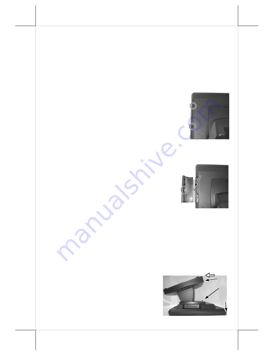
in  right  side  cover  of  the  LCD/touch  unit.  Remove  the  2 
circled screws in the right picture to remove the cover for side mount upgrade 
kit as viewed from back of the panel. 
 
Take  out  the  cable  inside  this  cover  as  arrowed  in  the 
right picture here and connect it to connector inside the 
side  mount  upgrade  kit  as  circled  in  the  same  picture. 
Gently  arrange  the  excessive  length  of  this  cable  back 
in  the  hole  and  screw-fit  it  back  to  the  position 
originally  occupied  by  the  cover.  Please  reserve  the 
cover  if  there  is  chance  to  have  the  side  mount  kit 
removed in the future. 


B.


Cable Connections 

In order to settle the touch  monitor properly in a point of sale system, all the 
cable connections have to be routed through its base. Therefore, please observe 
the  procedures  from  A  to  C  below  to  separate  the  main  unit  from  the  base 
stand assembly after all cables in connection area disconnected. 


Step A:

 Prepare a soft clean flat surface, such 

as a piece of cloth on the desk to seat 
the front surface of main unit after 
being adjusted to most horizontal 
position 

Step C:

 Slide the base stand assembly to separate 

the main unit from base stand 

Step B: 

Press the Lock/Release button to 

detach the base stand from main unit. 

A


C


B


Summary of Contents for LM-7117

Page 1: ...e the user at his own expense will be required to take whatever measures to correct the interference WARRANTY LIMITS Warranty will terminate automatically when the machine is opened by any person other than the authorized technicians The user should consult his her dealer for the problem happened Warranty voids if the user does not follow the instructions in application of this merchandise The man...

Page 2: ...llowing picture After take the PE form out from the carton please remove the PE form with extra care and make sure place the monitor and stand on a soft clean flat surface such as table and as show in the picture at the right side Please find the four holes in the top of stand Take the stand and align these four matching holes to the four matching pegs which are in the back on monitor After matchi...

Page 3: ...le Base Assembly Option SD 400W Logo Power Indicator Lock release lever Push in this direction to adjust the tilt angle of the display panel Control button area Lock release button to detach the main unit NXT button button OSD button button Power switch COM option RS232 VGA input USB B to Host 12 V DC input USB A to Devices ...

Page 4: ...connect it to connector inside the side mount upgrade kit as circled in the same picture Gently arrange the excessive length of this cable back in the hole and screw fit it back to the position originally occupied by the cover Please reserve the cover if there is chance to have the side mount kit removed in the future B Cable Connections In order to settle the touch monitor properly in a point of ...

Page 5: ...evices to LM 7117 TM 7117 at the type A connectors Please note that unlike usual USB HUB these USB devices won t be recognized by the host when LM 7117 TM 7117 are powered off C Option Wall Mount Kit Select a flat surface on wall of adequate strength and with proper ventilation and space condition Please use the right material to hold this monitor according to the wall material Drywall concrete so...

Page 6: ...one and duration Please go to Program Files and select Posiflex USB Touch Tools and then select Posiflex USB Touch Manager within the tools to engage this utility Most items in this utility should be easily understandable to average user Followings are just some reminders on some items Calibrate This button engages the Posiflex USB Touch Calibrator Hide Cursor This button hides or shows the mouse ...

Page 7: ... all changes to the parameters and closes the utility window Help This button provides explanations b USB touch calibrator This program helps re calibrating the touch position with the USB mouse emulation Please touch the calibration targets at each corner and a confirmation box that appear sequentially c USB touch edge acceleration tool Helps to find the hidden taskbar or thin scroll bar through ...

Page 8: ...aussing prior to recovery may accept only one direction in card reading If the fingerprint sensor option is installed in the side mount kit please find the most comfortable angle for the fingerprint taking operation in consideration of the LCD panel tilt angle and try to align the core of fingerprint in the sensing area IX LED MODULE INDICATION Green standby Blue power on When this touch monitor i...

Page 9: ...ns on items in sub menu are as below BRIGHTNESS CONTRAST ADJUST SUBMENU There are 3 icons in this submenu Press OSD button to select item or return to main menu Press NXT button to select among brightness contrast and exit BRIGHTNESS ADJUST When this item is selected there will be only the brightness icon with an adjustment indication bar under it between the main menu area and the video signal mo...

Page 10: ...XT button to select among the 3 colors Red Green and Blue respectively Press button to intensify that color Press to reduce Press OSD button to save the current setting and return to Color balance adjust submenu 4200K Pressing OSD button on this icon will set the color balance to a color temperature of 4200 degrees Kelvin 5000K Pressing OSD button on this icon will set the color balance to a color...

Page 11: ... POSITION When this item is selected there will be only the horizontal position icon with an adjustment indication bar under it between the main menu area and the video signal mode Press or button to shift the screen display to right or left Press OSD button to save the current setting and return to Geometry adjust submenu VERTICAL POSITION When this item is selected there will be only the vertica...

Page 12: ...rd Press to go upward Press OSD button to save the current setting and return to OSD submenu EXIT Return to Tools submenu RESET TO DEFAULT Pressing OSD button on this icon will set all parameters back to the status when the monitor left factory SMOOTHNESS SHARPNESS ADJUST When this item is selected there will be only the smoothness sharpness adjust icon with an adjustment indication bar under it b...

Page 13: ... 31 5 56 35 1 60 37 9 72 48 1 800 600 75 46 9 60 48 4 70 56 5 1024 768 75 60 60 64 1280 1024 75 80 XII TROUBLE SHOOTING In case of any malfunction please check the following points in sequence to resolve it 1 If there is no power indication please check the power connection 2 If there is no picture display with power LED on please check the video signal connection 3 If there is no touch function p...

Reviews: