background image


Part 17

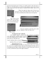
gap between the bottom side of front cover and the chassis at the left corner of 
front cover. Pull the front cover out from this opening to release the left side 
hook of front cover from the chassis as indicated by the hollow arrow in the 
picture above. 

Please then pull the bottom side of front cover 

forward to release the bottom hooks of front cover from 
the chassis as indicated by hollow arrow in left picture. 


Now pull the left 

side of front cover down a 
little to free it from the main 
cover as in the right picture. 


It may be required to push the power switch 

down to completely remove the front cover. 


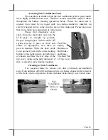
Cleaning for Front Ventilation 

Use vacuum cleaner to remove any dust or threads accumulation 

away from both the ventilation holes on front 
cover and ventilation grids on chassis exposed 
after removal of the front cover. 

Replacing Front Cover 

Follow the opposite procedure as removing the front cover to replace 

the front cover in position. Please make sure the all hooks on front cover  is 
well positioned into chassis. Please remember to check that the power switch is 
at “Off” position before power and signal connection. 


Front Ventilation Grids on Chassis 

Ventilation Holes on Front Cover 

Power Switch 

Summary of Contents for HT-2000 Series

Page 1: ...uding without limitation loss of data or profits resulting from the furnishing performance or use of this material This information is provided as is and Posiflex Inc expressly disclaims any warranties expressed implied or statutory including without limitation implied warranties of merchantability or fitness for particular purpose good title and against infringement The information in this manual...

Page 2: ...hole system till completely exhausted Repeatedly using it up or improper maintenance reduces the battery life dramatically Always fully recharge the battery at least once every 3 months if the battery is not connected Always disconnect the UPS battery from the system if the system is to be left OFF for more than 72 hours to prevent possible damage Only connect the UPS battery back right before you...

Page 3: ...This Open Standard Architecture ensures that this terminal can use the PC application software and development tools that are now inexpensively available and abundant The terminal is powered by most up to date CPU and provides a color TFT LCD screen with a resistive type touch control panel on sturdy and easily adjustable structure on top of the main unit It may be used as a self content unit or a...

Page 4: ... 2 cash drawers Modem Ring Up LAN Or Alarm Wake Up The HT 2000 series can be turned on automatically upon an incoming COM port Modem call or LAN status or data packet received on LAN or a preset time day week month Built in UPS function to support the system from intermittent power failure battery itself is an option Accidental power off protection The power switch is safely located at one side an...

Page 5: ...types of Posiflex programmable keyboards Most recommended KB 6000 KB 6200 series or KB 6600 m Bar Code Scanner Short range type near contact and long range type 250 mm for CD 3830 CCD scanners n POS printer Posiflex 9 pin dot matrix impact printer or Posiflex thermal printer of RS232 serial interface parallel interface USB interface or even wireless interface SYSTEM BOX CONTENTS When you receive t...

Page 6: ... whole installation operation of a half length PCI extension card involves cautiously accessing the interior of the system replacing the slot window metal plate applying the card and installing its driver Therefore only a computer expert can perform this operation on his own risk MAIN CONNECTION AREA The HT series is constructed for very easy maintenance Press inward both plastic buttons at lower ...

Page 7: ...he HT system this option is already installed in the delivery inside the back cable cover with its cable connected to one of the USB port This cable must be disconnected first if installed whenever the back cable cover is opened for any operation UPS BATTERY OPTION When the HT system is installed with the UPS battery the UPS battery is in the carton at delivery Please take it out and place it in t...

Page 8: ...stem this option is already installed in the delivery No matter the kit itself contains MSR only finger print sensor only or both options the connection to the HT system is one USB cable inserted to the extended USB port at top right edge of the system unit as circled in the upper picture at right After removing the plastic cover by pushing it side way the extended USB port can be found as marked ...

Page 9: ...arcode scanner instead of the PS 2 KB interface type PRINTER OPTION There are many models of Posiflex POS printers that can be applied in HT system These printers cover several interface technologies Please connect the printer to a COM port the LPT port or an USB port in the main connection area depending on the printer model and then connect its power adaptor It is also possible to control a Posi...

Page 10: ...ws system on HDD Posiflex provides recovery CD delivered with the hybrid terminal for the preloaded operating system The System Integrator shall take care of software restoration after OS recovered Use a Posiflex supplied USB interface external CDROM drive for such action Other brand CDROM drive may require its specific driver different from what supported in the recovery CD Please use the recover...

Page 11: ...nts must conform to local safety regulations UPS Battery option General care The UPS battery is consumable beyond product warranty Please definitely observe the alerts in beginning of this manual If the equipment is to be powered off for more than few days please always disconnect the battery from the system Reconnect it and turn on the system to recharge the battery for 1 2 hours every 3 months f...

Page 12: ...M1 For the HT system installed with the UPS function module a COM1 terminator will also be supplied Please always occupy COM1 serial port by a suitable serial device or this terminator If this port is left vacant or connected with something like a mouse the power switch management and the cash drawer control may fail to work correctly An RS232 MODEM is not applicable to this port It is recommended...

Page 13: ...r On Control The system may also turn on according to some preset conditions such as Modem Ring Up and Alarm Clock Wake Up or LAN Wake Up To utilize Modem Ring Up or Alarm Clock Wake Up function the user should enter the CMOS setup by pressing Del key at system boot up choose for PM Wake Up Events in Power Management Setup and make the Ring Power Up Control enabled for Modem Ring Up or select the ...

Page 14: ...t Turning this knob up or down changes the brightness of screen display accordingly Display Utility Driver The end user of the HT terminals is not supposed to install the utility drivers personally If an optional preloaded OS is ordered the required driver will be already installed in the preloaded OS However the driver will always be available over our web site http www posiflex com Touch Functio...

Page 15: ...desktop Touch the right button in this drawing Any touch on the screen after this action will result in a right button mouse click at the point touched After touching the left button in this drawing the screen touch will resume the left button function This program also controls the beep generated when the touch panel is touched the detail in right button click emulation and also provides touch pa...

Page 16: ...s and try to correct the situation when the system is off and cooled down You may power up the system again after the system cooled down and trouble cause removed However if the trouble remains please consult your dealer for possibly fan replacement on worn out USB There are in total six standard USB female connectors in the rear room All support the Universal Serial Bus Specification standard 2 0...

Page 17: ...s in the right picture It may be required to push the power switch down to completely remove the front cover Cleaning for Front Ventilation Use vacuum cleaner to remove any dust or threads accumulation away from both the ventilation holes on front cover and ventilation grids on chassis exposed after removal of the front cover Replacing Front Cover Follow the opposite procedure as removing the fron...

Page 18: ... to straight up position Prepare enough space in front of the HT system and lay a piece of clean soft clothe of appropriate size there to prevent damage With the back cable cover opened push in the circled spring button in the right picture on both sides of chassis and raise the rear edge of the top cover Apply some mild maneuver if there is already a pole display mounted Cleaning for Side Ventila...

Page 19: ...Part 19 ...

Page 20: ...Part 20 警告使用者 這是甲類的資訊產品 在居住的環 境 中 使 用 時 可 能 會 造 成 射 頻 干 擾 在這種情況下 使用者會被要 求採取某些適當的對策 T31454 ...

Reviews: