background image


2 - 14 

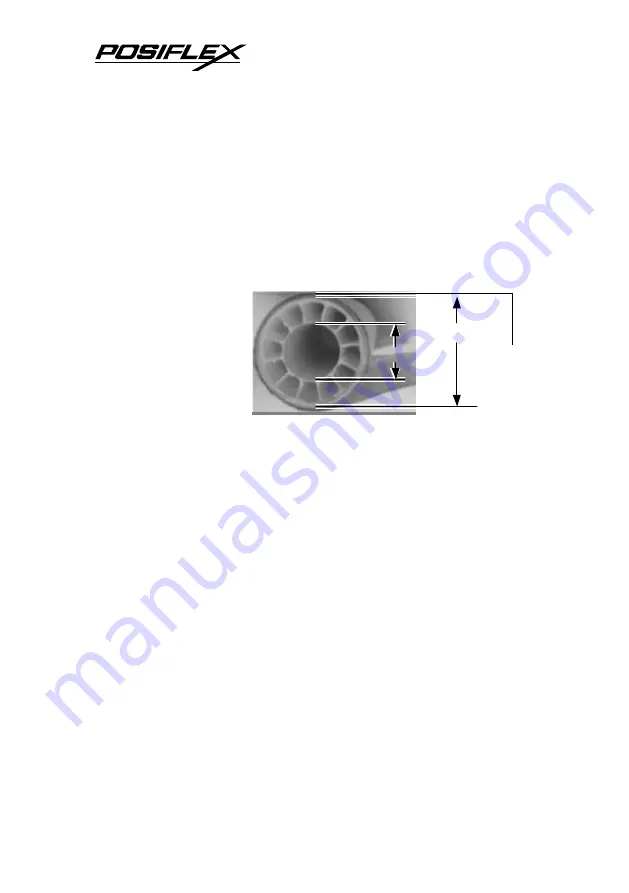
Slightly release the fixing screw to adjust the position of sensor 
head. The acceptable paper roll bobbin outer diameter is between 
18 and 22mm. This adjustment allows sensor activation on paper 
roll overall diameter between 21 and 23.6 mm unless for too light 
bobbins. Remember, for smaller roll diameter, the sensor head 
should go higher. 

2. 

Paper Roll Placement 

When the paper 

roll to put (back) in is 
already nearly used up, 
the paper roll must be 
placed in the way that 
the paper roll touches 
the sensor head from 
the outer surface but never allow the sensor head to ride on the 
bobbin body between the inner and outer diameter of the paper 
roll bobbin nor to go into the inner diameter of the paper roll 
bobbin. It is also noticed that some market available paper roll has 
extremely light bobbin, easily causing the paper roll to go off 
position when paper feeding with low remaining paper. In this 
case, the paper near end sensor may function abnormally and it 
would be a good solution to set in the setup window to have the 
printer to send busy only when input buffer is full and not based 
on every off line signal.  

3. 

Spacer Plate 

If the paper roll is of width less than the standard 80 / 58 

mm, it may run away from the paper near end sensor during 
application resulting in an error status. In this case, please stick 
the spacer plate to the wall opposite to the paper near end sensor 
in the paper roll compartment. Each spacer plate compensates 1 
mm paper roll width shortage. There will be 1 spacer plate in the 

Bobbin I.D. 

Bobbin O.D. 

Thermal 
Paper 
Surface 

Summary of Contents for Aura PP7700 Series

Page 1: ...eless POS Thermal Printer User s Guide IMPORTANT Please read carefully before using this printer Before opening the Top Hood make sure there is no paper jam or cutter jam trouble Read page 3 4 3 5 and Warranty Limit in the user s Manual ...

Page 2: ...when the machine is opened by any person other than the authorized technicians The user should consult his her dealer for the problem happened Warranty voids if the user does not follow the instructions in application of this merchandise The manufacturer is by no means responsible for any damage or hazard caused by improper application About This Manual This manual is aimed to assist the user to u...

Page 3: ...o Replace Paper 2 2 CONNECTION SET UP 2 2 Serial Connection 2 2 Wireless Connection 2 2 General concepts 2 2 Physical and driver installation 2 3 Making wireless connection 2 7 Automatic re connection at power on 2 9 Flexible wireless connection 2 9 Signal Detection to select a proper printer location 2 10 Peripheral Connection 2 11 Power Connection 2 12 Power On 2 12 Self Test 2 12 SPECIAL ADJUST...

Page 4: ...blems 3 2 Paper Jam Problems 3 4 Auto Cutter Problems 3 4 Graphic Printer Speed 3 5 Wireless Connection Concerns 3 5 Advanced Analysis Tool 3 7 SPECIFICATIONS 4 1 PRINTER 4 1 PAPER 4 1 POWER ADAPTOR 4 2 TECHNICAL INFORMATION 5 1 INTERFACES 5 1 Wireless Interface 5 1 Peripheral Interface 5 2 SETUP WINDOW 5 2 INTERNAL SWITCH 5 4 SOFTWARE COMMANDS 5 5 Paper Out Alarm 5 5 Enhancement Commands 5 5 CHAR...

Page 5: ...erforms thermal printing particularly designed for POS applications This unique wireless communication architecture not only frees the user from messy cabling setup in multiple host vs multiple printer environment but also provides the easiest adaptability for conventional POS software to utilize the cutting edge technology with least modification needs The Aura PP7700 series printer uses thermal ...

Page 6: ...f there is any discrepancy or problem contact your dealer immediately Be sure to save the packing materials in case the printer needs to be shipped at some point in the future The printer itself Thermal paper roll 80 mm wide ƒ One piece of spacer plate One of the power sources a Power adaptor power cord depend on country type ordered b Power supply cable when no power adaptor ordered This printer ...

Page 7: ...se or Simplified Chinese E MAIN PARTS ON THE EXTERIOR Front View Rear View Power Switch Antenna Serial Connector Power Connector Peripheral Connector Frame Ground Bottom Cover Power LED Error LED Paper Out LED FEED Switch Top Hood Top Cover Hood Release Power Switch Cutter Cover ...

Page 8: ...ose a place that is well ventilated and free of excessive dust smoke or fume Do not put the printer under direct sunlight or near a heater Avoid such environment with large number or size of metal objects in the neighborhood for siting of either the wireless printer or the wireless Dongle connected to the host Screws Window Plate Screw Setup Window ...

Page 9: ...a power outlet of a circuit shared with any equipment that uses a lot of power such as a copier or a coffee maker Do not touch any connector contacts to avoid possible electrostatic damage Do not allow the cut receipt to slide back into the cutter during the operation As this would lead to multiple cutting at the lower edge of a receipt and the multiple cut thin slips tend to cause mechanical malf...

Page 10: ...mal paper If thermal paper touches anything includes phthalic acid ester plasticizer for a long time the image formation ability may be reduced or the printed image may fade If thermal paper touches diazzo copy paper immediately after copying the printed surface may be discolored Thermal paper must not be stored with the printed surfaces against each other as the printing may be transferred betwee...

Page 11: ... printer to release the hood 2 Raise the released hood wide open manually 3 Drop the thermal paper roll inside the printer in the orientation as shown in the picture 4 Close the hood back leaving the tail of the paper roll coming out of the opening between the hood and the top cover Tear off excessive paper ...

Page 12: ... printer and consequently possibility for paper jam B CONNECTION SET UP 1 Serial Connection All the external connectors are in the recessed area at the rear bottom The serial connector should be used only in specific technical applications like debug testing or firmware upgrade Nothing should be connected to this port in normal operation 2 Wireless Connection a General concepts The standard PP7700...

Page 13: ...ow the arrangement of the application program accordingly However if the software did not take care of the wireless connection the user may install the relevant driver prior to the execution of the application software The driver can be found together in delivery of the wireless printer or the Posiflex Product Information CD of version 1 9 or above or please visit our web http www posiflex com or ...

Page 14: ...ll COM ports to be used for wireless connection before driver installation and select the COM ports used one by one if requested in the installation program Reboot system after installation complete Detail illustrations are as below First copy or decompress the drivers to a subfolder in the host system where Dongle DG2000 is attached Then in the host system click Start Settings Control Panel Syste...

Page 15: ...specific location Advanced Don t search I will choose the driver to install Have Disk Browse and find the subfolder where the drivers were stored Select ComBtDrv inf Click Open OK Posiflex Wireless Dongle and a warning message on digital signature will show up in Hardware Update Wizard ...

Page 16: ...2 6 Ignore this message and click Next a warning dialogue box will pop up Select Continue Anyway to exit the Hardware Installation warning dialogue box ...

Page 17: ...ogram if it covers the wireless connection because it may then utilize some more practical naming of the wireless printer in use Follow procedures below for first time connecting a wireless printer to the Dongle if the application program does not take care of this part 2 Please find under the bottom of the wireless printer PP7700 that you want to connect a BT ID printed on a label near the serial...

Page 18: ...ne Dongle connected in a host system please do the setup procedure for one Dongle at a time 4 Check in the above screen that when the Dongle is well installed and recognized by the software a 12 digit Dongle ID will appear in the field for HOST BT Address Double check the installation if it still shows NONE here Do a Query Printer and in the PRINTER field all BT ID of the wireless printers within ...

Page 19: ...tion on fixed port Dongle printer pair relationship with multiple Dongles and multiple printers in the overall space but enjoying the convenience of no messy cables This is default supported in Posiflex wireless connection 2 If for any reason this automatic reconnection at power up is disabled you may re activate this function by including a program shortcut in the system StartUp menu Please inclu...

Page 20: ...printer and that wireless printer can be freed for connection to other Dongle if required 3 Signal Detection to select a proper printer location The Posiflex wireless printer PP7700 is designed and manufactured to operate within 100 meters distance from the correspondent Dongle in free space However in the real world the Electro Magnetic wave propagation is greatly influenced by the surrounding en...

Page 21: ...up Please adjust the position of the host system and Dongle antenna direction when necessary It is quite commonly experienced that several centimeter move or turning the directions of either the host or the printer can make significant influences Please also take into consideration the operation area of operating personnel as human body usually influences wireless communication a lot After fixing ...

Page 22: ...kward to release the internal latch Failure to do this could damage the power plug Such damage is considered as an artificial destruction and is not covered by the warranty 6 Power On When all the above cable connections are made correctly you may connect your power adaptor to the wall outlet Make sure that the type of power cord and the voltage requirement of the power adaptor meet the local powe...

Page 23: ...AL ADJUSTMENTS 1 Paper Near End Sensor The near end sensor for paper roll in the printer is now able to have the printer work with paper rolls of several bobbin sizes Please refer to the picture at right from inside the paper roll compartment that there are a fixing screw and a sensor head in the wall Fixing Screw Sensor Head ...

Page 24: ...ner diameter of the paper roll bobbin It is also noticed that some market available paper roll has extremely light bobbin easily causing the paper roll to go off position when paper feeding with low remaining paper In this case the paper near end sensor may function abnormally and it would be a good solution to set in the setup window to have the printer to send busy only when input buffer is full...

Page 25: ... logo printed on top of each slip it is also highly suggested to print the logo and necessary paper feeding to make 12 mm paper advance right after each cut to prevent curling up and jamming of paper front edge inside the paper exit slot 5 Wall Mount Application In wall mount application the paper near end sensor will not have proper operation and it is suggested to set in the setup window to have...

Page 26: ......

Page 27: ...se use soft hair brush or compressed air to clear away any dust or paper scraps accumulation inside the printer Check also the area of the auto cutter regularly C PRINT HEAD CLEANING The print head is located underneath the roll paper passage at the exit as in the picture below You can clean the thermal elements of the print head and paper sensor gently using a cotton swab moistened with isopropyl...

Page 28: ...he paper roll is not installed or is at or near the end Install a new paper roll If the Paper Out LED is OFF please check if the print hood is properly closed There are 2 internal check points inside the printer to assure the locking of the hood for a decent printing Therefore any dislocation of the hood may cause an error status and inhibition to printing Press down the hood at middle of the open...

Page 29: ...vice person Poor printing quality Contaminants like paper scraps and dusts on the thermal print head can lower the print quality drastically Clean the print head as described in previous section Printer trembles when printing Since PP7700 prints at 180 mm sec that is extremely high speed the printer may tremble due to frequent engagement of the brake and acceleration of the motor Such situation in...

Page 30: ... staple or paper clip or excessive paper scraps fall into the auto cutter mechanism the auto cutter may lock up and so does the print hood In such case please pull the cutter cover forward to expose the cutter mechanism Apply some mechanical assistance below to reset the cutter blade back to its home position Please lift up if exist a transparent protective cover over the adjustment wheel Turn thi...

Page 31: ...ned during normal operation maybe for paper roll change or else and all E M field conditions remain unchanged The Error LED on PP7700 will lit The wireless connection driver in the host system will indicate loss of connection and keep trying for reconnection till time out If the error status of PP7700 is expelled before the host time out the wireless connection resumes automatically without troubl...

Page 32: ...cover automatically after the blocking or the interference is removed However when it happens during printing there will be data loss Therefore it is also quite advisable for the application program to provide an option for end user to send command to the printer to clear the residual memory of last printing and resend the last printing job Wireless connection broken by accidents on host side If t...

Page 33: ...roblems To start the dump mode Turn off printer Open print hood Hold down FEED button while turning printer on Close the hood To stop the dump mode Press the FEED button to print out the last line Turn off the printer During dump mode The host still can access connect send data to PP7700 through the wireless connection At PP7700 all commands except DLE EOT and DLE ENQ are disabled ...

Page 34: ......

Page 35: ...nt Segmentation Vertical Shift Max 0 06 mm Paper feed method Friction auto feed Paper load method Drop and use Auto cutter capability Partial cut 1 point at center left Manual cutter Saw tooth blade Dot Pitch 0 125 x 0 125 mm Input power type DC Input voltage 24 V 5 Dimension mm 148 W x 199 D x 144 H Weight 1 35 Kg net B PAPER Paper type Thermal roll paper Paper roll formation External side is hea...

Page 36: ...UIREMENT INPUT VOLTAGE 100 V AC 250 V AC INPUT FREQUENCY 50 60 HZ INPUT CURRENT 1 5 A MAX 115 V AC OUTPUT VOLTAGE 24 V DC OUTPUT POWER 60 W STATIC LOAD 0 A 2 5 A OUTPUT REGULATION 5 MTBF 30 000 HRS EMI STANDARDS VDE B FCC B VCCI B ...

Page 37: ...m ITEM FUNCTION Setup Utility Search for wireless printer in range of each Dongle discover and register a virtual COM port for each printer connect Dedicated Connection One Printer for each Dongle Direct I O control or OPOS driver can be utilized to control printer No AP modification required Non dedicated Connection Multiple printers for one Dongle or multiple printers for multiple Dongles Dynami...

Page 38: ...onnect the CR1 plug to the cash drawer CRA to be opened by command Esc p 1 n1 n2 and the CR2 plug to the cash drawer CRB to be opened by command Esc p 0 n1 n2 PIN Definition Description 1 FG Frame ground 2 CRB Drawer kick for cash drawer controlled by software command Esc p 0 n1 n2 3 SENSE Input peripheral status 4 VCC 24 V DC supply 5 CRA Drawer kick for cash drawer controlled by software command...

Page 39: ...it For switch position 5 if the switch is set to ON the busy signal is sent to host only when input buffer is full When it is set to OFF busy signal is sent to host whenever an off line status occurs Therefore signals including the paper near end detect will generate busy signal to the host Consequently the printing may be stopped even when there is still a long way to go before the paper roll is ...

Page 40: ...he printer Remove 4 screws from bottom of printer and remove the plastic bottom cover with the power switch pressed The 4 position DIP switch seats beside the 8 position DIP switch for setup window with the switch position counting starts from the nearest side to the 8 position DIP switch This 4 position DIP switch works as following Switch position Setting Effect ê Function ON OFF 1 Factory inter...

Page 41: ...site http www posiflex com tw http www posiflextw com or http www posiflexusa com for detail description of the supported commands if required 1 Paper Out Alarm When Paper End signal is detected the printer keeps on intensive beeping and stops receiving data till the signal is neutralized When Paper Near End signal is detected the printer gives a beep every 3 seconds and stops receiving data 2 Enh...

Page 42: ...all connect the cable from the bell to the peripheral connector on the printer Then use this command with m set to 0 and both n1 and n2 set to 255 The printer will be able to drive the kitchen bell for about half a second on each such command If this command is sent to the printer multiple times consecutively the bell will ring for about half a second and rest for also about half a second then rin...

Page 43: ...te language system can be achieved by adding each relevant font chip in standard model Japanese Kanji Korean KCS5601 Traditional Chinese Big 5 Simplified Chinese GB2312 The international character sets supported in basic ASCII range include USA France Germany UK Denmark I Sweden Italy Spain Japan Norway Denmark II Spain II Latin America Korea for character set code from 0 to D and Ex Jugoslavia fo...

Page 44: ...5 8 The user may visit our web at http www posiflex com tw or http www posiflex com for a view of the fonts in the code pages and character sets ...

Reviews: