Eurekaweg 4 2991 ZB Barendrecht
T +31 (0)180 629009
www.poseidon-bv.nl
Ordernumber
Date
25-01-2015
Ref.erence
STA-STF
Version
2
Status
Final
Page
13
of
20
2.3.3 Replacement of the complete seal or overhaul.
If the vessel is slipped and the shaft is dismounted and the seal as a complete item is to be dismounted
for an overhaul than follow these instructions are to be followed up.
1.
When the shaft is to be pulled, always dismount the seal complete seal from the tube so it
rest on the shaft.
2.
Close the seal isolation valves of the water lubrication system.
3.
Clean the shaft right behind the seal thoroughly.
4.
Remove the water inlet
5.
Remove the stand by seal inlet
6.
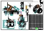
Remove screws (item 25)
7.
Gasket (item 14) needs to be replaced by the new gasket!! So the old (item 14) needs to be
removed completely and both seal house face and stern tube face require thoroughly cleaning.
8.
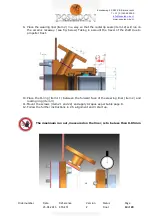
The wearing liner (item 2) was removed earlier when the shaft was removed.
9.
Remove screws (item 23),
10.
Remove the retaining ring (item 4).
11.
Pull the first radial lip seal out by using a small hook.
12.
Take the first spacer ring out of the housing. There are 2 threaded holes in the face of the ring
that you can use to put a M6 screw in that will help pulling it out.
13.
Remove the 2
nd
radial lip seal as you did the first one
14.
Pull out the stand by seal together with the support ring (item 7).
15.
Check if the seal seats and rings are still in good condition and clean all faces thoroughly.
Remove any grease or dirt.
16.
If all is OK, parts are clean we can start mounting the new stand by seal (item 13) and radial lip
seals (item 12) and assemble partly the Pegasus seal again. ( they liner will be positioned if the
shaft is in place again. !!! Note!! BEFORE mounting the shaft do NOT forget to slide the wearing
liner (item 2), with the new O-rings (item 11) and the Clamp ring (item 3) over the shaft.
17.
Place the new stand by seal (item 13) around the support ring (item nr 7).
18.
Slide the stand by seal and support ring back in position. (do NOT yet mount the set screws item
24!!)
19.
Take the spring from each seal and unscrew the joint. Turn the spring around the shaft until the
connection of both end of the spring are visible and, holding one end in each hand, twist the
other end a few turns counter clockwise.
20.
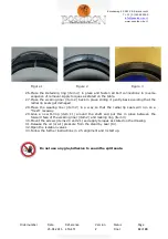
Take both spring ends , wind them counter clockwise , bring the ends together and release the
spring ends to obtain a proper engagement. To avoid any ‘ curl
-
in’ tendency at the split, the
precautions, detailed in figurers 1
–
3 (chapter B) shall always be followed.
21.
Pass the seal around the shaft and lift the spring into the groove in the seal lip.
22.
Ensure that the two spring ends match perfectly, with the split at the top side.
23.
Push the seal evenly into the chamber and also press firmly against the back side of the housing.
24.
During the installation of forward split radial lip seal (item 12), grease (according to parts list)
shall be added.
25.
Do not grease the seal facing the bearing site as otherwise grease can come in the system.
26.
Place the retaining ring (item 4) in place and fasten all bolt connections in reverse sequence of
removal. Apply torques as stated on the drawing.
27.
Tight the set screws (item 24).
28.
After the shaft is mounted again the wearing liner (item 2) can be positioned and mounted.
29.
Place the wearingliner back in place sliding it gently back avoiding that the radial lip seals get
damaged.
30.
Position the wearing liner in a way so that the radial lip seals will run on a “ fresh” raceway.
31.
New O-ring (item 11) are to be put in place between the forw face of the wearing liner (item 2)
and Clamp ring (item 3).
32.
Mount the screws (items 20 and 21) and apply torques as stated on the table
33.
Follow the further instructions in 2.5 alignment and 3 start up.


