WARNING
Instruction Manual
w
PE 100-T
11
In case of overstepping the prescriptive limits, see chapter
4.5. Trouble-shooting
3.3.3. Intake air quality
Ensure intake air is free from
noxious gas (CO), exhaust fumes
and solvent vapour. On units em
ploying petrol or diesel engine it is most important to
use an intake hose and observe that only clean air is
drawn in. The intake hose is also recommended for
units with electric engine. When operating the unit in
areas with possibly high CO contents, the CO removal
filter cartridge is recommended for electric driven
units, also. Note that for CO contents of more than 25
ppmV in the intake air the allowed limits cannot be
guaranteed even with a CO removal filter cartridge,
resulting in a life-threatening CO concentration! Also,
due to chemical reaction of CO with hopcalite, warm
ing up of the cartridge and danger of fire may result.
At routine tests, CO
2
values beyond the permissible values
are noted from time to time. Closer investigations often
show that the compressed air is taken from rooms in which
one or more persons are working. At insufficient ventila
tion, the CO
2
value in the surrounding air can increase quite
fast because of the exhaling of CO
2.
CO
2
values from 1,000
to 5,000 ppmv in workrooms are not unusual (MAK-value
(max. workroom concentration) is 5,000 ppmv). Another
additional increase is caused by cigarette smoking, produc
ing approx. 2g CO
2
(
2,000 ppmv) per cigarette. These
pollutions add up to the basic pollution of approx. 400
ppmv. The technically caused excessive increase of CO
2
during the filling process and the CO
2
peak at taking the
unit into operation.
Because of the reasons stated
above and for your own security, the filling of breath
ing air bottles is not allowed in rooms used as work
rooms.
3.3.4. Scavenging the compressor unit
CO
2
is present in the atmosphere with a natural amount of
350 to 400 ppm
V
. The molecular sieve used in the purifier
for drying the breathing air is, as well as other capabilities,
able to adsorb CO
2
which is accumulated in the cartridge.
After shut-down of the compressor, adsorbed CO
2
may be
desorbed again due to the partial pressure decrease. The
now free CO
2
then gets washed out of the cartridge when
the compressor is started again. To avoid increased CO
2
contents in the compressed breathing air, we recommend
to flush the compressor unit 1 to 2 minutes prior to con
necting the bottles, i.e. to let the air escape into the sur
roundings.
Scavenging procedure
1.
Ensure that no bottle is connected to the compres
sor.
2.
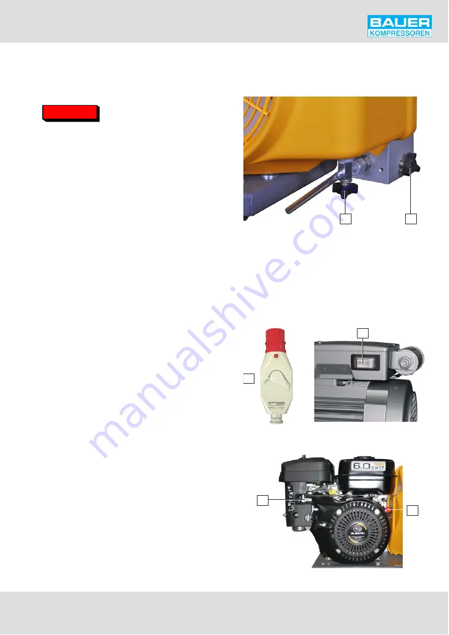
Open condensate drain tap (1, Fig. 5) of interme
diate separator (on petrol units additionally the con
densate drain tap (2, Fig. 5) of final separator) to
unload the compressor during the starting phase.
Fig. 5
Condensate drain taps
1
2
3.
Switch on the unit:
•
PE 100-TE: Shift switch (1, Fig. 6) to position I.
•
PE 100-TW: Press switch (2, Fig. 6) to position I.
•
PE 100-TB: Shift switch (1, Fig. 7) to position I. Set
choke (2, Fig. 7) to position START. Start engine with
recoil starter. As soon as motor runs smoothly return
choke to normal operating position.
Fig. 6
Motorschutzschalter
1
2
Fig. 7
Petrol engine
2
1
Summary of Contents for PE 100-T
Page 1: ...High Pressure Breathing Air Compressors Instruction manual...
Page 2: ......
Page 39: ...Instruction Manual w PE 100 T 33...
Page 40: ......
Page 41: ...Instruction Manual w PE 100 T 35 8 ANNEX Schematic diagram Lubricating oil list Parts list...
Page 42: ...Instruction Manual w PE 100 T 36...


