background image

17


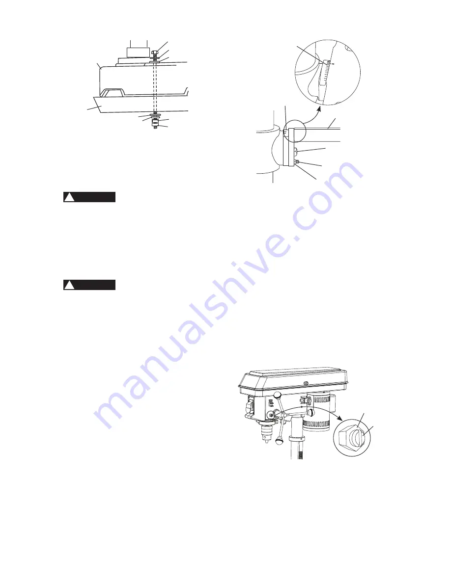
Fig. M

SPINDLE / QUILL (FIG. N)

Rotate the feed handles counterclockwise 

to lower spindle to its lowest position. Hold 

the chuck and move it front to back. If there 

is excessive play, proceed with the following 

adjustments:

1.  Loosen the lock nut (1) located on the 

right side of the drill press by using a 


10 mm wrench.

2.  Turn the screw (2) clockwise to eliminate 

the play, using a slotted screwdriver, but 

without obstructing the upward movement 

of the spindle. (A little play in the spindle 

is normal.)

3.  Tighten the lock nut (1).


Fig. N


Fig. L

ADJUSTMENTS INSTRUCTIONS

NOTE: 

All the adjustments for the operation

of the drill press have been completed at the

factory. Due to normal wear and use, some

occasional readjustments may be necessary.

To avoid injury from an accidental start, 

ALWAYS make sure the switch is in the 

“OFF” position, the switch key is removed, 

and the plug is not connected to the power 

source outlet before making adjustments.

BEVEL DRILLING (FIG. M)

To prevent personal injury, always 

disconnect the plug from the power 

source when making any adjustments.

NOTE:

 A bevel scale has been included

to measure approximate bevel angles. If

precision is necessary, a square or other

measuring tool should be used to position

the table. To use the bevel scale (1):

1.  TIGHTEN the nut (2) on the locking pin (3)


using a 10 mm or adjustable wrench 

clockwise to RELEASE the locking pin (3) 

from the table support.

2.  Loosen the bevel lock bolt (4) using a 


17 mm or adjustable wrench.

3.  Tilt the table (5) to desired bevel angle 

that will shown on the bevel scale (1).

4.  Tighten the bevel lock bolt (4).

5.  To return the table to horizontal position, 

loosen the bevel lock bolt (4), return the 

table (5) to the 0° position.

6.  Return the nut (2) on locking pin (3) to the 

OUTSIDE END OF THREADS. Gently 

tap locking pin (3) until it is seated in the 

mating hole of the table bracket. Hand 

tighten the nut (2).

WARNING

!

1

2

5

3

4

6

7

8

9

WARNING

!

5

2

4

1

1

3

1

2

Summary of Contents for PCXB620DP

Page 1: ...PULGADAS PERFORADORA DE COLUMNA CATALOG NUMBER PCXB620DP Instruction Manual Manuel d instructions Manual de instrucciones www portercable com INSTRUCTIVO DE OPERACI N CENTROS DE SERVICIO Y P LIZA DE...

Page 2: ...he tool use proper circuit protection Use a separate electrical circuit for your tools The drill press is wired at the factory for 120 Volt operation It must be connected to a 120 V 3 2 AMP branch cir...

Page 3: ...often you do this type of work To reduce your exposure to these chemicals work in a well ventilated area and work with approved safety equipment such as those dust masks that are specially designed to...

Page 4: ...an attachment to do a job for which it was not designed 10 USE PROPER EXTENSION CORDS Make sure your extension cord is in good condition When using an extension cord be sure to use one heavy enough t...

Page 5: ...NNING UNATTENDED TURN THE POWER OFF Do not walk away from a running tool until the blade comes to a complete stop and the tool is unplugged from the power source 21 DO NOT OVERREACH Keep proper footin...

Page 6: ...he workpiece at high speeds DO NOT USE fly cutters or multiple part hole cutters as they can come apart or become unbalanced in use Following good safety practices when using drill presses is a must M...

Page 7: ...EJECTING TYPE CHUCK KEY as provided with the drill press Tighten the bit securely in the chuck The chuck key can be thrown at a high velocity if not removed causing risk for injury 27 DO NOT FORCE DR...

Page 8: ...nding instructions or if you are not certain the tool is properly grounded USE only 3 wire extension cords that have three pronged grounding plugs with three pole receptacles that accept the tool s pl...

Page 9: ...ed to temporarily connect this plug to a two contact grounded receptacle The adapter Fig 2 has a rigid lug extending from it that MUST be connected to a permanent earth ground such as a properly groun...

Page 10: ...eavy and should be lifted with care If needed get the assistance of someone to lift and move the drill press If any part is missing or damaged do not attempt to assemble the drill press or plug in the...

Page 11: ...11 UNPACKING YOUR DRILL PRESS A B C D E G F H...

Page 12: ...ank handle Rack Table bracket Motor Chuck key holder Pulley cover Mounting holes Table Chuck Column ON OFF switch with safety key Hex head lock screws ON OFF LED light switch Depth scale pointer Quill...

Page 13: ...stability holes are provided in the base to bolt drill press to the floor See ADDITIONAL SAFETY RULES FOR DRILL PRESSES BACKUP MATERIAL A piece of scrap wood placed between the workpiece and table The...

Page 14: ...fted with the help of two people OR MORE to safely assemble it ASSEMBLING COLUMN TO BASE FIG A 1 Position the base 2 on a flat and stable work surface must be able to support 100 lbs 2 Place the colum...

Page 15: ...Drill Press head is very heavy and MUST be lifted with the help of 2 people OR MORE to safely assemble the Drill Press head on the column 1 Carefully lift the head 1 and slide it onto the column 2 Ma...

Page 16: ...r the chuck to the lowest position 2 Place a ball joint separator not shown above the chuck and tap it lightly with a hammer or rubber mallet to cause the chuck to drop from the spindle Never hit the...

Page 17: ...e plug is not connected to the power source outlet before making adjustments BEVEL DRILLING FIG M To prevent personal injury always disconnect the plug from the power source when making any adjustment...

Page 18: ...PRING FIG O The quill return spring may need adjustment if the quill return speed is too fast or too slow This spring is located on the left side of the drill head 1 Lower the table for additional cle...

Page 19: ...40 1100 620 ON OFF SWITCH FIG S The ON OFF switch has a removable safety key With the safety key removed from the switch unauthorized and hazardous use by children and others is minimized 1 To turn th...

Page 20: ...ld the feed handle at this position 4 Spin the lower nut 3 down to contact the depth stop lug 4 5 Spin the upper nut 5 down and tighten against the lower nut 3 6 The drill bit 2 now will stop after tr...

Page 21: ...tion it against the LEFT side of the column If the workpiece or the backup material is not long enough to reach the column Failure to do this could result in personal injury FIG X 3 For a small piece...

Page 22: ...o cut 2 Feeding too slowly might cause the drill bit to burn Feeding too rapidly might cause the belt or drill to slip tear the workpiece loose or break the drill bit 3 When drilling metal it is neces...

Page 23: ...sure product SAFETY and RELIABILITY repairs maintenance and adjustment other than those listed in this manual should be performed by authorized service centers or other qualified service organizations...

Page 24: ...9730 Attention Product Service Be sure to include all of the information shown on the nameplate of your tool model number type serial number etc WARNING PROBLEM PROBLEM CAUSE SUGGESTED CORRECTIVE ACTI...

Page 25: ...it not properly installed in chuck 4 Chuck not properly installed 1 Replace drill bit 2 Replace bearings 3 Install drill properly See Section BASIC DRILL PRESS OPERATION and ASSEMBLY 4 Install chuck p...

Page 26: ...HD SCREW M5 0 8 12 6 X769 HEX NUT M6 2 X77P PULLEY COVER ASS Y 1 X76A FLAT WASHER 6 1 X77W SPINDLE PULLEY 1 X76B DEPTH SCALE BASE 1 X77X PULLEY SET NUT M8 10 3 X76H TERMINAL 1 X7AZ BATTERY BOX ASS Y 1...

Page 27: ...6S2 X76T X76U X76V X76Q X76P X76N2 X75N3 X75Q X7B5 X762 X7B4 X75Z X75X X761 X760 X7B6 X7592 X76X2 X7B7 X77X X7AZ X7792 X778 X75C X77B X77C X77D4 X77F X77G X77H X77L X77X2 X774 X773 X772 X7712 X7702 X7...

Page 28: ...rks for one or more Porter Cable and Delta products 2 BY 4 890TM Air America AIRBOSSTM Auto Set B O S S Bammer Biesemeyer Builders Saw Charge Air Charge Air Pro CONTRACTOR SUPERDUTY Contractor s Saw D...

Reviews: