Automatic boiler for wood pellets
31
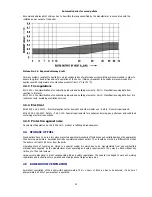
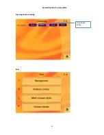
Setting of a proper equithermal curve
Setting or changing servomotor timing
5.8
CHECKING TASKS BEFORE BOILER FIRST OPERATION
The authorized service technician preparing the boiler for its initial operation must perform the following tasks before
start-up. He will record results of all checking tasks – will fill a Certificate of Introduction to Service (Putting boiler into
operation) – see appendix 1 -
Report of putting the boiler KP into operation
.
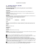
Check water volume in the heating system and corresponding water pressure.
Check whether fittings between the boiler and the heating system are open.
Check the heating system for leaks at all new connections – pressure test done by a professional firm.
Check the chimney connection (must be tight and safe to prevent escape of flue gases). Chimney and boiler
connection must have valid inspection.
Check functionality of circulatory pump and its venting.
The electrical grid outlet must be always accessible. New electrical outlet must have a valid inspection..
Check the heating chamber and ash receptacles. Clean from possible dirt.
Check tank filling by specified fuel.
Check operating parameters for the specific boiler type.
Confirm that installation meets building regulations for the country in which it is installed – by providing of
Building Regulations Compliance Certificate or a Local Authority Building Notice.
When flue or chimney is provided as part of the installation the installer must provide information essential to its
correct application with permanently displayed way.
6
BOILER SERVICE AND MAINTANANCE DURING OPERATION
Service and maintenance intervals are directly dependent on the type and quality of used fuel.
If recommended fuel – wood pellets with clearly guaranteed quality parameters is used, service and maintenance
of the product during operation is very simple.
6.1
SERVICE
Pellet boiler service comprises of only two tasks. The necessary presumption is use of guaranteed fuel endorsed by the
manufacturer. As a standard, use wood pellets with the 6mm or 8mm diameter.
6.1.1
Refuelling
The fuel level must be maintained in such height that there is always a minimum of 10cm pellets above the F1 feeder
inlet. Insufficient pellet volume may result in irregular dispensing or boiler fire extinction.
You will be told the presumed refuelling interval by the service technician according to your specific configuration.
Note:
The refuelling interval cannot be prescribed ambiguously.
It depends on:
Fuel bin size
The average boiler output in the particular time interval
Quality of used fuel
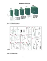
Anticipated interval – see anticipated burning times in table 1.
Note:
A seasonal tank may be installed to the boiler. Refuelling is controlled automatically or manually.
6.1.2
Emptying of the external container
It is generally true that ash must be removed any time the ash level exceeds 2cm level below the side edges of the
external ash container.
Summary of Contents for KP 12S
Page 1: ......
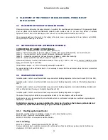
Page 17: ...Automatic boiler for wood pellets 16 Picture No 9 Feeder F1 4 5 1 4 5 2 4 5 3 4 5 4 4 5 5 ...
Page 28: ...Automatic boiler for wood pellets 27 Picture No 20 Ceramic grate parts placement guide ...
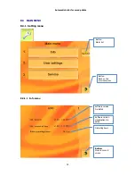
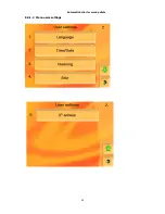
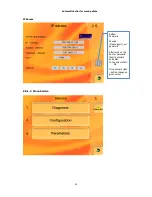
Page 41: ...Automatic boiler for wood pellets 40 8 3 1 2 Menu users settings ...
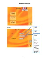
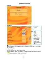
Page 43: ...Automatic boiler for wood pellets 42 Cleaning an ash removing Skin Time window setting ...
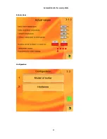
Page 46: ...Automatic boiler for wood pellets 45 Actual values Configuration ...
Page 52: ...Automatic boiler for wood pellets 51 Cleaning Ash removing USB Time window setting ...
Page 53: ...Automatic boiler for wood pellets 52 Load from USB Save on USB ...
Page 58: ...Automatic boiler for wood pellets 57 ...
Page 60: ...Automatic boiler for wood pellets 59 ...
Page 61: ...Automatic boiler for wood pellets 60 i ...
Page 63: ...62 Picture No 24 Principle of the modulation ...
Page 64: ...63 Picture No 25 Directory information consumption wood pellets for boiler family KP ...
Page 65: ...64 Picture No 26 Circuit diagram control unit ...
Page 66: ...65 Picture No 27 Circuit diagram module HZS 533 ...
Page 67: ...66 Picture No 28 Circuit diagram HZS 533 HZS 535 ...
Page 73: ...72 11 APPENDIX 2 REPORT ON THE PUTTING THE BOILER KP INTO OPERATION ...
Page 74: ...73 12 APPENDIX 3 SELF ADHESIVE LABEL IMPORTANT SAFETY INFORMATION ...

