


Installing and Starting Up
2
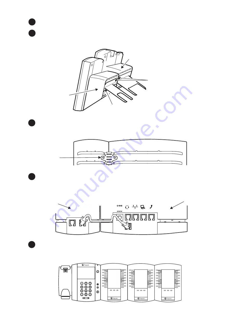
4
To connect another Expansion Module, attach another Cable Connector between the
AUX 2 port on the first Expansion Module and the AUX 1 port on the second
Expansion Module. You can connect a maximum of three Expansion Modules to one
phone, as shown next.
Turn the phone and Expansion Module upside down on the table. Insert the Cable
Connector between the AUX port on the phone, and the AUX 1 port on the
Expansion Module. Thread the cable through the Cable Grooves on the Expansion
Module and phone. If the phone is connected to the network, the Expansion Module
will automatically power on and start up.
5
Position the phone and Expansion Module next to each other on a flat, level surface.
Position them as closely together as you can. Then, locate the holes for the thumb
screws; the holes are located between the top-most and middle stand slot.
1
Connect the base stand to your Expansion Module at the same angle as your
phone’s stand.
3
Hold the metal bracket so that the four tabs face away from you, and the arrow on
the back of the bracket points up. Position the holes in the metal bracket over the
thumb screw holes. The four tabs on the bracket fit in the top-most and middle stand
slots. Insert the thumb screws in the holes, and finger tighten.
Metal
Bracket
AUX 1
AUX 2
48V
LAN
HEADSET
HANDSET
PC
AUX
Back of
VVX Phone
Back of
VVX Phone
Holes for
thumb screws.
Position holes in
metal bracket
over these holes.
Middle
stand slot
Back of
Expansion
Module
Back of
Expansion
Module


