background image

Polycom® RealPresence® Video Protect 500 Setup Sheet

2

3

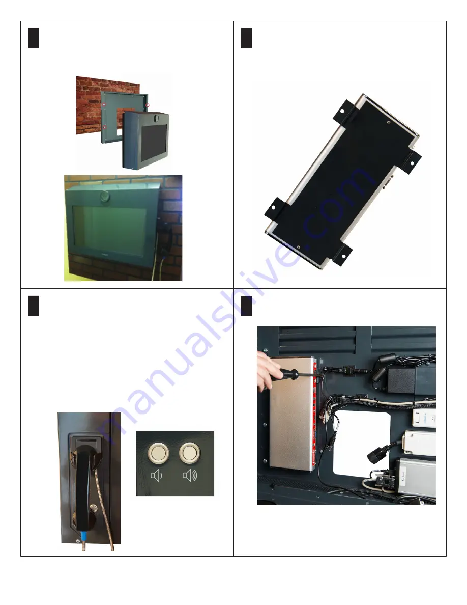
A handset, handset cradle, and volume up and
down buttons are mounted to the right side of the
enclosure. You can move the handset plate to the
left side of the enclosure or remove it completely.

For hands-free mode using the mic on the EagleEye
Acoustic camera, remove the handset plate and
replace it with the supplied blank plate. Connect the
3.5mm-3.5mm cable from the codec Audio Out 
port to the display Audio In port. Also replace the
protective camera lens with the lens that has 
pre-drilled holes.

Open the enclosure and hang the enclosure on
the wall, using five screws per side. Note that two
screws on each side align with two keyhole
slots in each side of the enclosure.

4

5

6

Remove the codec mounting bracket from the
enclosure by removing the four M3 x 10 screws. 
Attach the codec mounting bracket to the back
of the codec, using two M3 x 8 Phillips pan head
screws.

Install the codec and bracket to the system, using
the four screws removed earlier. 

Summary of Contents for RealPresence Video Protect 500

Page 1: ...concrete anchors 1 4 20 x 1 1 4 hex cap screws and 1 4 washers not supplied If you are mounting to a surface other than brick or concrete use appropriate mounting hardware or seek professional assistance The installer should have a plan for connecting the system using one of the following options A hole drilled in the wall with network and AC ready for system AC wall outlet and or a LAN wall outle...

Page 2: ...3 5mm cable from the codec Audio Out port to the display Audio In port Also replace the protective camera lens with the lens that has pre drilled holes Open the enclosure and hang the enclosure on the wall using five screws per side Note that two screws on each side align with two keyhole slots in each side of the enclosure 4 5 6 Remove the codec mounting bracket from the enclosure by removing the...

Page 3: ...ckets and screws Attach the power supply to the enclosure using the supplied bracket and screws 8 Attach the cables to the codec Most cables are pre wired and labeled Refer to the wiring diagrams at the end of this document for details 7 Using the supplied zip ties secure the camera cable to the monitor mounting bracket 10 ...

Page 4: ...network cable to the codec or connect a bare wire directly to the network junction block 13 Connect the camera cable to the codec 11 12 To securely store the remote use the supplied Velcro to attach the remote to the bracket on the inside cover of the Video Protect system Before storing the remote inside the unit Polycom recommends that you remove the USB rechargeable battery by This prevents the ...

Page 5: ... the following codec settings Admin Settings General Settings Serial Ports Mode RS 232 Mode Control Baud Rate 9600 Parity None Data Bits 8 Stop Bits 1 RS 232 Flow Control None Login Mode None The Video Protect 500 does not support the use of passwords on the serial port Admin Settings Audio Video Audio Audio Input Playback Options Handset Audio Input Level 5 default Admin Settings General Settings...

Page 6: ...27 0 0 1 or other Mains Input Rating Voltage 100 240VAC 50 60Hz Current 2 7A max Physical size and weight 23 1 2 W x 19 H x 6 5 8 D without handset 27 W x 19 H x 6 5 8 D with handset 55 lbs 6 Polycom RealPresence Video Protect 500 Setup Sheet Regulatory Notices This equipment is intended for indoor use only Do not use a power cord that is damaged This could cause fire or electric shock Contact the...

Page 7: ...7 Polycom RealPresence Video Protect 500 Setup Sheet Shield Wiring Diagram ...

Page 8: ...8 Polycom RealPresence Video Protect 500 Setup Sheet Handset Wiring Diagram ...

Reviews: