


Poly EduCart 2 Setup Sheet
4
9
Remove your display from packaging. If possible, leave
the display on the bottom portion of the packaging.
For mounting purposes, Poly supplies four long M8 × 25
screws and spacers to use between the H frame and the
display. Note: Depending on the display selected, you
may require M6 or M8 screws that are not supplied.
Attach the H frame to the rear of the display using
the holes circled in red below. If the packaging interferes,
either cut the foam or lift the display out.
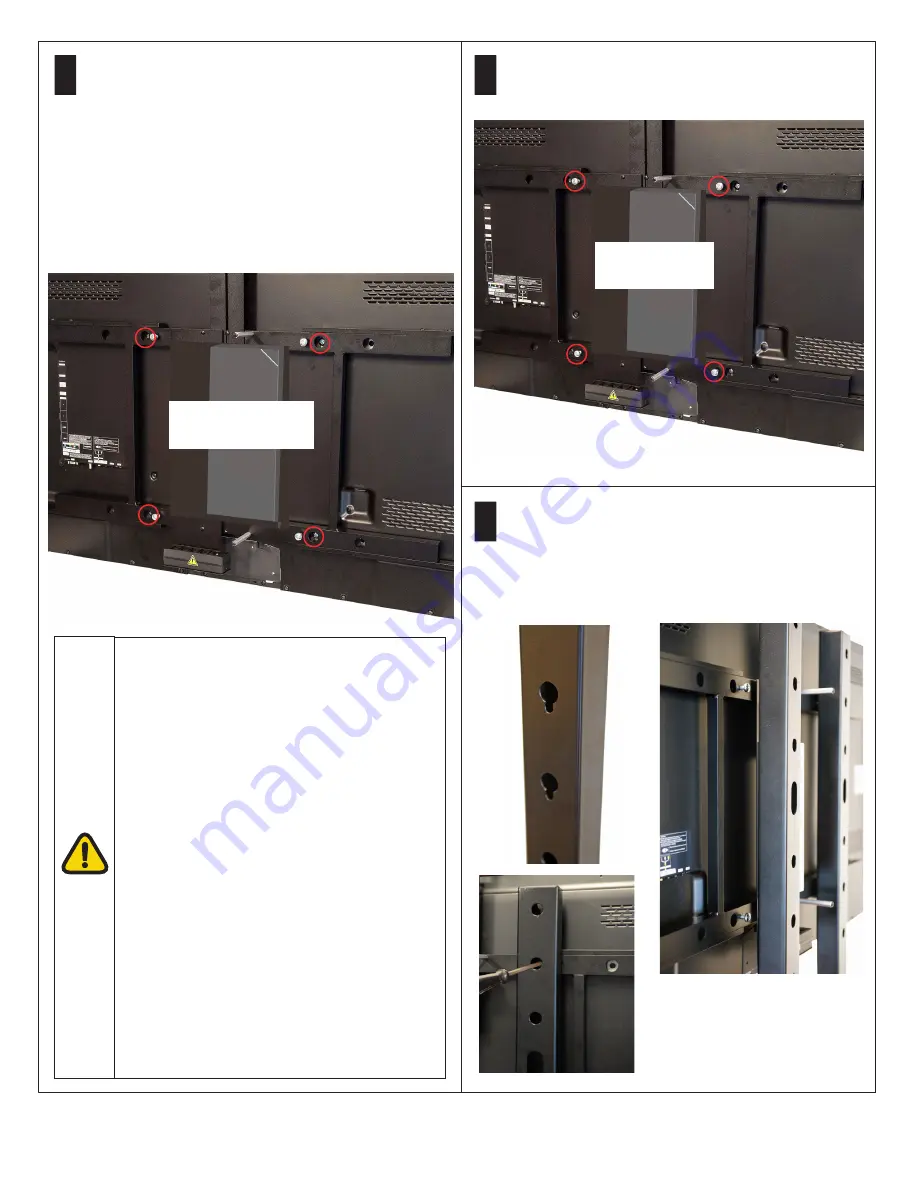
7
8
Insert four M8 × 16 screws on the back of the frame
(circled in red below) and hand tighten to about half way.
The screws must be loose to fit onto the cart.
Ensure that the cart casters are locked. With a person
on each side, lift the display, by the handles, onto the
cart at the desired height. Ensure that all four M8
screws installed in step 8 are hooked into the keyhole
slots in the cart poles. Tighten the four M8 screws
through the holes.
Attach H frame using
holes circled in red.
M8 x 16 screws
circled in red.
Maximum supported displays:
The display used must have VESA mounting
400 mm × 400 mm, or 400 mm × 600 mm.
To avoid risk of toppling over, displays must not
exceed any of the following tested parameters.
High Position
Diagonal 65”
Weight 39 kg (86 lb.)
W: 1458.6 mm × D: 50.0 mm × H: 836.4 mm
(57.4” × 2.0” × 32.9”)
Mid Position
Diagonal 75”
Weight 64 kg (141 lb.)
W: 1735.0 mm × D: 79.1 mm × H: 1017.4 mm
(68.3” × 3.1” × 40.0”)
Low Position
Diagonal 75”
Weight 64 kg (141 lb.)
W: 1735.0 mm × D: 79.1 mm × H: 1017.4 mm
(68.3” × 3.1” × 40.0”)


