


Politec Srl | Manual MANA DT SMA + DT3
–
Ver 2.5.2
21
8.7 START UP
8.7.1 TX COLUMN
After you remove the cover and shield, make connections to the mains power transformer and tamper
circuit.
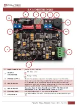
1.
Check the various connections: the power transformer to the circuit, the battery, the power
circuit to circuit and transmitter cavities TX (See pp. 9, 12-13).
2.
Power board, check the LED lights on Mains power adapter and three power LEDs with V-Test
jumper inserted in position 1-2 (see pp. 12-13).
3.
Turn OFF the switch which is on cavity TX. (See page 14).
4.
Verify that is in position ON one of the four switches of the "channel selector" tab, TX (same as
RX) See page. 9.
5.
Insert the jumper in position 2-3 to verify that LEDs output and VCC (see page 10).
6.
Replace the two jumpers in the resting position.
8.7.2 RX COLUMN
After you remove the cover and shield, make connections to the mains power transformer and tamper
circuit.
1.
Check the various connections: the power transformer to the circuit, the battery, the power
circuit to circuit and transmitter cavities RX (Vedi pagg. 10-13).
2.
Power board, check the LED lights on Mains power adapter and three power LEDs with V-Test
jumper inserted in position 1-2 (Vedi pagg. 12-13).
3.
Turn OFF the switch which is on cavity RX.(Vedi Pag.14).
4.
Verify that is in position ON one of the four switches of the "channel selector" tab(same as TX)
(Vedi pagg. 10-11).
5.
Check the "voltages" on the receiver, turning in ON position the switch N.10 "selector function",
and displaying the desired tension (5, 9, 13.8 volts) with dip No 7-8-9 (See pp. 11-12).
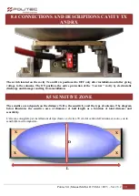
Perform an initial visual alignment between the two columns (TX and RX).
Horizontal orientation:
Loosen the screws and turn the column.
Vertical orientation:
Loosen the screws of the handling system of the parable, and rotate.
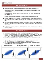
Verify that on the board RX the leds alarm and Channel are on. Otherwise proceed with the electronic
alignment, however, be made to obtain a precise alignment.


