ENGINE
3.20
OIL FLOW
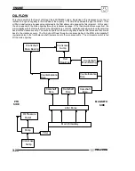
This chart describes the flow of oil through the 600/700/800 engine. Beginning in the crankcase sump, the oil
is drawn through an oil galley to the feed side of the oil pump. The oil is then pumped through the oil filter. If the
oil filter is obstructed, a bypass valve contained in the filter allows oil to bypass the filter element. At this point,
the oil is supplied to the main oil galley through a crankcase passage. Oil is then diverted three ways from the
main oil galley, with the first path entering the camshaft bores, onto the rear balance shaft journal and then draining
back into the crankcase sump. The second oil path from the main oil galley feeds the lifter bores and then drains
back to the crankcase sump. The third oil path flows through a crankcase galley to the MAG side crankshaft
journal and also to the front balance shaft journal and onto the crankcase sump. The oil pressure switch is fed
off the main oil galley.
Main Oil Gallery
Counterbalance
Bore
Lifter Bores
Camshaft
Bore
Camshaft
Bore
Camshaft
Bore
Crankshaft
Rod
Bearings
Counterbalance
Bore
Oil Pressure
Relief
Crankshaft
Main Bearing
Crankcase
Sump
Sump
Crankcase
Pump
Filter
MAGNETO
SIDE
PTO
SIDE
Main Bearing
Summary of Contents for Sportsman 800 Efi 2005
Page 116: ...ENGINE 3 62 NOTES ...
Page 136: ...FUEL SYSTEM FUEL INJECTION 4 20 NOTES ...
Page 186: ...CLUTCH 6 30 NOTES ...
Page 256: ...BRAKES 9 24 NOTES ...
Page 292: ...ELECTRICAL 10 36 BASIC WINCH WIRING 2005 ATV MODELS 2005 ATV WINCH WIRING DIAGRAM ...
Page 300: ...ELECTRICAL 10 44 NOTES ...
Page 301: ...ELECTRICAL 10 39 WIRING DIAGRAM 2005 SPORTSMAN 700 800 EFI Stator ...
Page 302: ...ELECTRICAL 10 40 WIRING DIAGRAM 2005 SPORTSMAN 700 800 EFI ...


